Page 6
Installation and Maintenance Manual form 185
2.3.2 To avoid over-tightening any of the supporting nuts,
we recommend the following torques for all standard
installations:
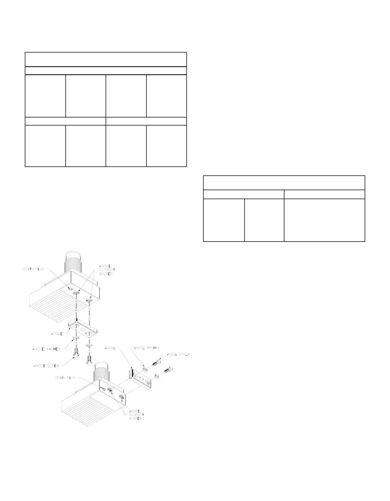
2.3.3 Anodes are standard equipment with copper-nickel
units. They minimize the eects of galvanic corrosion
and should be replaced when deteriorated. The life
of these plates varies with localities.
2.3.4 Attach the anodes using the special bolts and
washers supplied with the unit. They can be found
in a cardboard box inside the unit shipping box. See
Figure 10.
FIG.10 Anode Attachment Detail
NOTE: Anode replacement kits, including anodes,
screws, and washers, can be ordered from
the factory. They are available with zinc
anodes or aluminum anodes upon request.
Please provide the model number of your
GRIDCOOLER® Keel Cooler to ensure the
proper replacement anodes are sent.
2.4 ALUMINUM INSTALLATIONS
2.4.1 Aluminum GRIDCOOLER Keel Coolers should be
installed on unpainted aluminum hulls only.
2.4.2 The 1/4-inch mounting gaskets supplied with the unit
must be used to provide proper spacing between
the cooler and the ship’s hull.
2.4.3 To avoid over-tightening any of the supporting nuts,
we recommend the following torques for all normal
installations:
2.4.4 Most aluminum units have tapered threads on the
nipples and no hose connectors (see installation
drawing). These units can be piped directly to the
engine, provided flexible couplings are used to
remove engine vibration between the engine and
the cooler.
2.4.5 If a wire reinforced rubber hose is used to connect
the unit to the engine, put a screw-on coupling over
the cooler nozzle threads.
2.4.6 Aluminum GRIDCOOLER Keel Coolers do not use
anodes.
2.5 PLUMBING
NOTE: Prior to installing cooler, flush entire piping
system to remove any debris.
2.5.1 Remove the orange nozzle plugs from the
GRIDCOOLER unit before hooking up the plumbing
to the cooler.
2.5.2 Engines equipped with inboard raw water heat
exchangers may not be able to be converted to
keel cooling, please consult your engine dealer and
Fernstrum representative for guidance.
2.5.3 As a rule-of-thumb, the expansion tank for your
cooling system should be able to hold approximately
COPPER-NICKEL UNIT
NUT TORQUES FT.-LBS. (KG-M)
NOZZLE THREAD SIZE
¾”
19mm
50 - 60
(7 - 8)
HEADER STUD
SUPPORT BOLT
1 - 1 ½”
25 - 38mm
75 - 100
(10 - 14)
2”
51 mm
125 - 150
(17 - 21)
2 ½ - 3 ½”
63 - 89mm
200 - 250
(28 - 35)
⅝ - ¾”
16 - 19mm
35 - 40
(5 - 5 ½)
1”
25 mm
50 - 60
(7 - 8)
½ - ¾”
13 - 19mm
20 - 25
(3 - 3 ½)
ALUMINUM UNIT
NUT TORQUES FT-LBS (KG-M)
NOZZLE THREAD
1 ½ - 3”
38 - 76mm
125 - 150
(17 - 21)
⅝”
16mm
20 - 25
(3 - 3 ½)
1”
25 mm
75 - 100
(10 - 14)
SUPPORT BOLT