Installation and Maintenance Manual form 185
Page 5
2.0 INSTALLATION
Once you have decided on the correct location, use
the following steps as a guideline for installing your
GRIDCOOLER® Keel Cooler.
2.1 MAKING HOLES
2.1.1 Measure the distance between the inlet & outlet
nozzles from center to center (also measure to the
centers of the support studs when applicable) before
cutting holes for them in the ship’s hull.
2.1.2 Make the holes through the hull 1/4 in. (6.4 mm)
diameter oversized.
2.1.3 Make sure that the hull surfaces where the unit will
be mounted are smooth and properly aligned (on
steel hulls, if you burn the holes, grind the edges
smooth afterwards). This will allow the gaskets to
seal properly and ensure that no undue stress will be
placed on the cooler.
2.2 FITTING UP
2.2.1 Under normal conditions, the compression of the
mounting gaskets puts sucient tension on the
nozzle nuts (and support bolt nuts when applicable)
to prevent them from working loose. To seal out
water, apply a bead of sealant to the exterior of the
gaskets, and around the points where the nozzles
and support bolts penetrate the hull before assembly.
2.2.2 Remember to tighten the nuts again, after the
caulking has set.
2.3 COPPER-NICKEL INSTALLATION
2.3.1 Mounting gaskets supplied with the GRIDCOOLER
Keel Cooler must be used to provide proper spacing
between the unit and the ship’s hull. See Figure 9.
For exterior gasket thickness see the chart below, all
exterior gaskets are available in ¼” on request
NOTE: INSULATORS: Insulators for galvanic isolation
of through-hull installation studs and nozzles
are available upon request at time of purchase.
When requesting the insulators, provide hull
thickness so the insulators can be supplied at
the proper length.
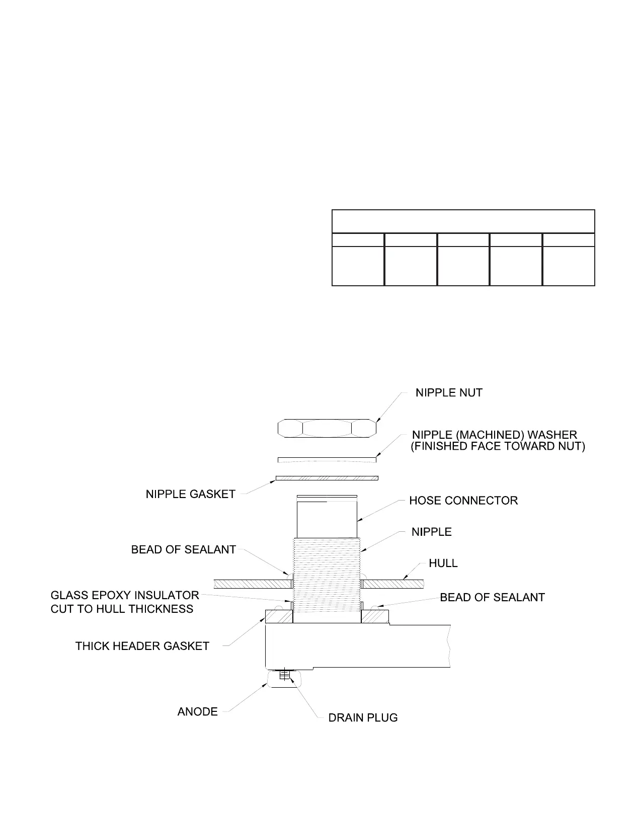
FIG.9 Mounting Parts Placement
NOTE: IF CONCAVE WASHERS ARE
USED, MAKE SURE CONCAVE SIDE
IS DOWN ON GASKET. FOR NIPPLE
WASHERS THAT ARE CAST, PLACE THE
ROUGH SIDE AGAINST THE GASKET.
EXTERIOR GASKET THICKNESS
B
¼”
6.4mm
½”
12.7mm
¼”
6.4mm
½”
12.7mm
BN
C CN
D
¾”
19mm