33
The maximum air pressure for cleaning purposes must be
below 205 kPa (30 psi). The maximum water pressure for
cleaning purposes must be below 275 kPa (40 psi).
Engine Maintenance
For engine maintenance schedules and procedures, please
refer to the engine operator's manual.
Containing Spilled Fluids and Proper
Disposal of Waste
Make sure that fluids are contained when performing
inspection, maintenance, testing, adjustment, and repair
of the unit. Be prepared to collect the fluid with suitable
leakproof containers before opening or disassembling any
component containing fluids. Do not pour waste onto the
ground, down a drain, or into any source of water.
Improper disposal of waste can threaten the environment.
Dispose of all fluids according to local regulations and
mandates.
Electronic Fuel Injection (EFI) System -
EFI Models
EFI is an electronically-controlled fuel management system
which is monitored by an Electronic Control Unit (ECU). A
Malfunction Indicator Lamp (M.I.L.) will illuminate if problems
or faults are detected. Servicing by an authorized dealer is
necessary.
CAUTION
Do not disconnect or reconnect ECU wiring harness
connector or any individual components with the ignition
switch in the "ON" position. This can send a damaging
voltage spike through the ECU.
Unplug harness from ECU before performing any welding
on equipment.
Inspect Muffler and Spark Arrester
Inspect the muffler for cracks, corrosion, or other damage.
Remove the spark arrester, if equipped, and inspect
for damage or carbon blockage. If replacement parts
are required, make sure to use only original equipment
replacement parts.
WARNING
Replacement parts must be the same and installed in the
same position as the original parts or fire could result.
Fuse Location and Identification
The electrical system for this unit is equipped with two
replaceable fuses. See the chart below for the circuit,
amperage, and approximate location of the fuses.
Circuit Amperage Approximate
Location
Main 25 amp Instrument control
panel.
PTO Clutch 15 amp Behind the seat on
the left hand side
of the unit.
Some models are equipped with a Starter Relay Jumper
Harness that features 15 amp inline fuse that is locatednear
the battery of the unit.The following units features this
second 15 amp fuse:
• Models with Briggs & Stratton 61G877 engine in serial
number range 4002218815 and above: 5901872,
5901881, 5902039, 5902064, 5902068 & 5902118
• Models with Briggs & Stratton 613777 engine in serial
number range4002180241 and above: 5901937,
5901938, 5902034, 5902035 & 5902067
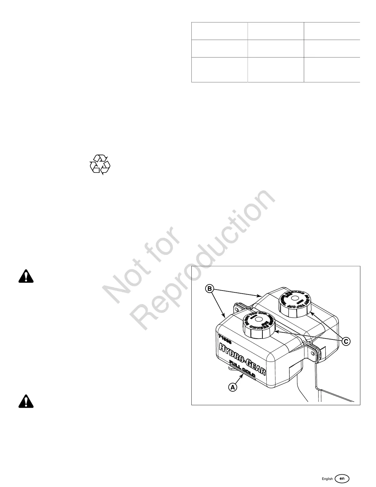
Check / Fill Transmission Oil Level
This unit is equipped with two transmission oil tanks. One
transmission oil tank only supplies oil to one transmission.
The level of oil in both transmission tanks must be checked,
and if necessary, filled.
Oil Type: SAE 20W-50 motor oil
1. Locate the transmission oil tanks (B, Figure 34) by raising
the seat plate of the unit.
2. Check the oil level when the unit is cold. The oil should be
up to the "FULL COLD" mark (A) on the transmission oil
tanks (B). If the oil is below this level, proceed to step #3.
34
3. Before removing the tank cap (C), make sure that the
area around the tank cap and fill neck of the tank is free
of dust, dirt, and other debris. Remove the tank caps.
4. Add oil up to the "FULL COLD" mark.
5. Re-install the tank cap.
6. After adding oil to the tanks, it may be necessary to purge
air from the hydraulic system. If the unit is not driving