48 ferrismowers.com
16. Run the mower under no-load condition for about five (5)
minutes to break in the new belts.
Transmission Drive Belt Replacement
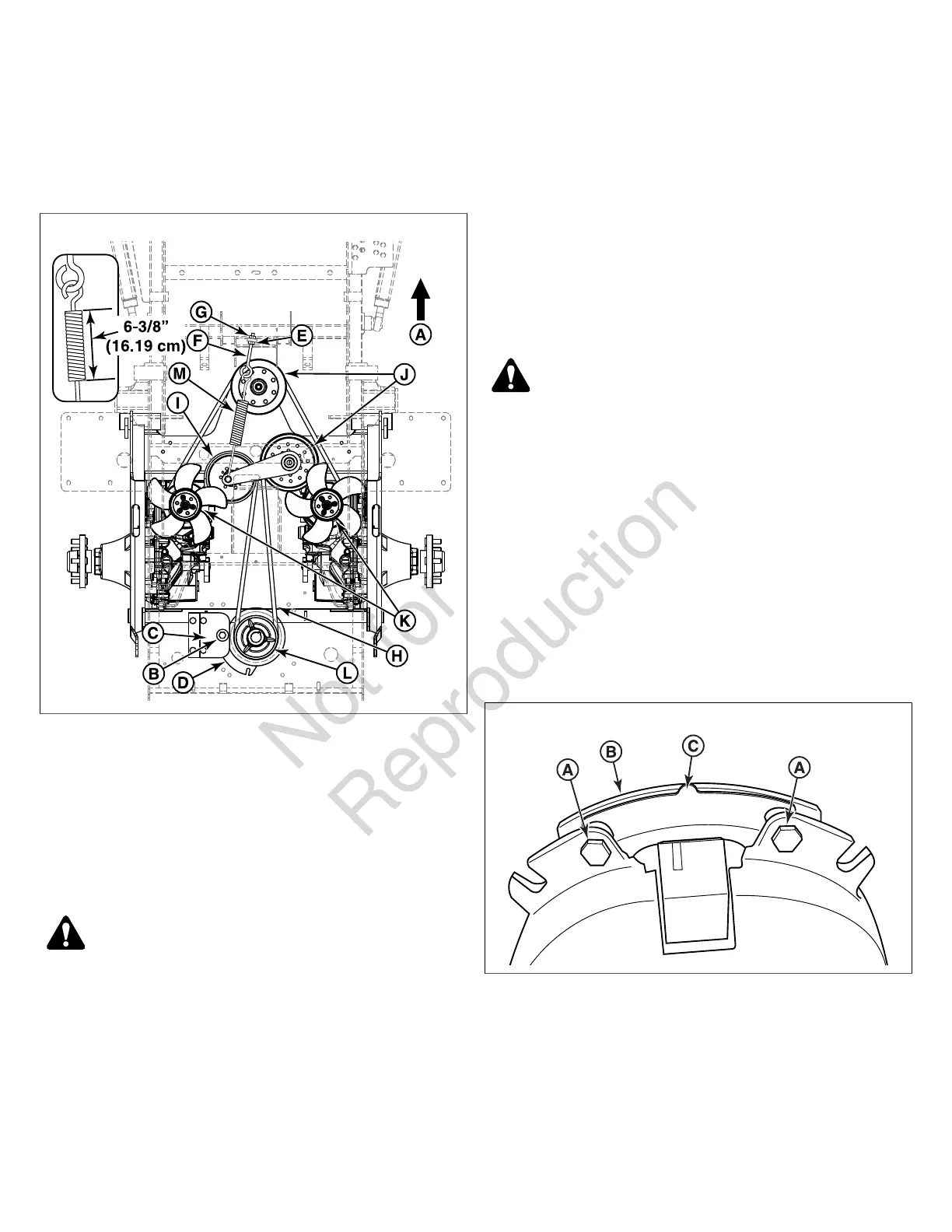
The illustration depicts the transmission drive belt setup as
seen from the top side of the unit and the arrow (A, Figure 70)
indicates the front of the unit.
70
1. Park the zero-turn riding mower on a smooth, level
surface such as a concrete floor. Disengage the PTO,
engage the parking brake, turn off the ignition, and
remove the key.
2. Remove the mower belt. See Long Left Hand Deck Belt
Replacement for removal instructions.
3. Remove the hardware (B) that secures the clutch anchor
pad (C) to the PTO clutch (D) and disconnect the wire
harness from the PTO clutch.
WARNING
STORED ENERGY DEVICE: Improper release of the belt
tension spring can result in personal injury. Use extreme
caution when removing the spring.
4. Loosen the jam nut (E) on the spring anchor eye bolt (F).
5. Loosen the adjustment nut (G) on the spring anchor
eye bolt to release the majority of the belt tension. Use
caution to remove the nut to completely release the
tension.
6. Remove the old belt and replace with a new one (H).
Make sure the V-side of the belt runs in the grooves
of the adjustable idler pulley (I), the front stationary
idler pulleys (J), both transmission pulleys (K), and the
crankshaft pulley (L).
7. Re-install the spring anchor eye bolt into the spring
anchor tab and loosely fasten the adjustment nut.
8. Tighten the nut until the spring (M) achieves a coil-to-coil
measurement of 6-3/8" (16.19 cm).
9. Tighten the jam nut.
10. Re-install the clutch anchor pad to the PTO clutch
and secure using the hardware previously removed.
Reconnect the wire harness to the PTO clutch.
11. Re-install the mower belt. See Long Left Hand Deck Belt
Replacement for re-installation instructions.
Electric PTO Clutch Adjustment
WARNING
To avoid serious injury, perform adjustments only with the
engine stopped, the ignition key removed, and the unit
parked on level ground.
Check the electric PTO clutch adjustment after the initial
25 hour break-in period and then after every 100 hours of
operation. If the electric PTO clutch is slipping or the electric
PTO clutch will not engage, the air gap can be adjusted by
removing the re-gap shim to allow the electric PTO clutch to
function.
1. Loosen both brake mounting bolts (A, Figure 71) 1/2 to 1
full turn as shown in Figure 71.
Note:Do not remove the brake pole (B) from the electric PTO
clutch. The brake pole must remain in the correct position to
ensure proper brake torque.
71
2. Using needle nose pliers, grasp the tab of the re-gap
shim (C) and remove the re-gap shim from the electric
PTO clutch.
3. Re-torque each brake mounting bolt to 10 ft. lbs. (13,5
Nm).
4. Using a .010" thick feeler gauge (A, Figure 72), verify that
the gap is present between the rotor (B) and armature
face (C) on both sides of the brake pole as shown in
Figure 72.