39
2. Remove the center hardware (D).
3. Move the head rest assembly up and down until the
desired head rest height is achieved and the hole in the
seat align with one of the four (4) holes (E) in the head
rest assembly.
4. Install the center hardware into the head rest assembly
and the back of the seat.
5. Tighten the outer hardware.
Ground Speed Control Lever Adjustment
The control levers can be adjusted in three ways. The
alignment of the control levers, the placement of the levers
(how close the ends are to one another) and the height of the
levers can be adjusted.
To Adjust the Handle Alignment
Loosen the mount bolts (A, Figure55) and pivot the lever(s)
(C) to align with each other.
55
To Adjust the Handle Placement
Loosen the jam nuts and adjust the placement bolt (B) in or
out to properly adjust the lever end spacing.
To Adjust the Handle Height
Remove the mounting hardware and reposition the handle
either up or down from its original position. You will need to
adjust the handle alignment again as described above.
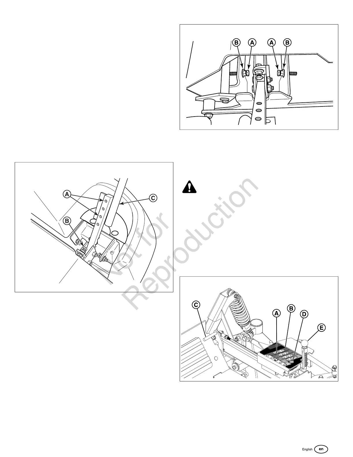
Speed Balancing Adjustment
If the rider veers to the right or left when the ground speed
control levers are in the maximum forward position, the top
speed of each of these levers can be balanced by turning the
adjustment bolt(s) (A, Figure56). Only adjust the speed of the
wheel that is traveling faster.
56
To Reduce the Speed of the Faster Wheel
1. Loosen the securing nut (B).
2. Turn the top speed adjustment boltcounter-clockwiseto
reduce the speed.
3. Retighten the securing nut when adjustment is complete.
WARNING
DO NOT adjust the tractor for a faster overall speed
forward or reverse than it was designed for.
Cutting Height Adjustment
The cutting height adjustment pin (A, Figure 57) controls
the cutting height of the mower deck. The cutting height
is adjustable between 1-1/2" (3,8 cm) and 6" (15,2 cm) in
1/4" (0,64 cm) increments.
Note:Make sure that the pin is inserted into the holes inboth
upper and lower plates of the pin box (B).
57
1. While sitting in the operator's seat, press the deck lift
pedal (C) forward to raise the mower deck until it locks
into the 6" (15,2 cm) position. Do not hold the pedal down
after the mower deck locks into the 6" (15,2 cm) position.
 Loading...