26
EN
cod. 3540S131 - 12/2009 (Rev. 00)
Room thermostat (optional)
B
IMPORTANT: THE ROOM THERMOSTAT MUST HAVE VOLTAGE-FREE
CONTACTS. CONNECTING 230 V TO THE ROOM THERMOSTAT TERMI-
NALS WILL PERMANENTLY DAMAGE THE ELECTRONIC BOARD.
When connecting time controls or a timer, do not take the power supply for
these devices from their breaking contacts Their power supply must be by
means of direct connection from the mains or with batteries, depending on the
kind of device.
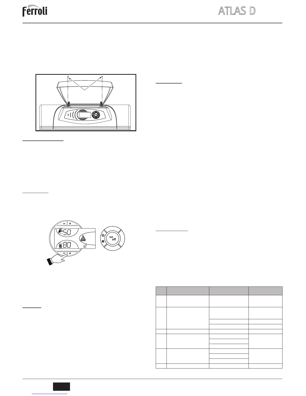
Accessing the electrical terminal block
Undo the two screws “A” located on the top part of the control panel and remove the
cover.
fig. 17 - Accessing the terminal board
3.6 Connection to the flue
The unit must be connected to a flue designed and built in compliance with current reg-
ulations. The pipe between the boiler and flue must be made from material suitable for
the purpose, i.e. heat and corrosion resistant. Ensure the seal at the joints and insulate
the entire pipe between boiler and flue, to prevent the formation of condensate.
4. SERVICE AND MAINTENANCE
All adjustment, conversion, start-up and maintenance operations described below must
only be carried out by Qualified Personnel (meeting the professional technical require-
ments prescribed by current regulations) such as those of the Local After-Sales Techni-
cal Service.
FERROLI declines any liability for damage and/or injury caused by unqualified and un-
authorised persons tampering with the unit.
4.1 Adjustments
TEST mode activation
Press the heating buttons (part. 3 and 4 - fig. 1) at the same time for 5 seconds to ac-
tivate TEST mode. The boiler lights at maximum power.
The heating symbol (detail 24 - fig. 1) and DHW symbol (detail 12 - fig. 1) flash on the
display.
fig. 18 - Operation in TEST mode
To deactivate TEST mode, repeat the activation sequence.
In any case, TEST mode is automatically deactivated after 15 minutes.
Burner adjustment
Boiler efficiency and correct operation depend above all on accurate burner adjustments.
Carefully follow the Manufacturer's instructions. The two-stage burners must have the
first stage adjusted to a power level not below the boiler's rated min. power. The power
of the second stage must not be higher than the boiler's rated max. power.
4.2 Start-up
B
Checks to be made at first lighting, and after all maintenance operations that
involved disconnecting from the systems or an intervention on safety devices
or parts of the boiler:
Before lighting the boiler
• Open any on-off valves between the boiler and the systems.
• Check the seal of the fuel system.
• Check correct prefilling of the expansion tank.
• Fill the water system and make sure that all air contained in the boiler and the sys-
tem has been vented, by opening the air valve on the boiler and any air valves on
the system.
• Make sure there are no water leaks in the system, domestic hot water circuits, con-
nections or boiler.
• Check correct connection of the electrical system and efficiency of the earthing sys-
tem
• Make sure there are no flammable liquids or materials in the immediate vicinity of
the boiler
Checks during operation
• Turn the unit on as described in sec. 2.3.
• Check the seal of the fuel circuit and water systems.
• Check the efficiency of the flue and air-fume ducts during boiler operation.
• Make sure the water is circulating properly between the boiler and systems.
• Check correct boiler lighting by performing various tests, turning it on and off with
the room thermostat or remote control.
• Make sure the fuel consumption indicated on the meter matches that given in the
technical data table on sec. 5.3.
• Ensure the seal of the fumebox and burner door.
• Make sure the burner works properly. This check must be made with the special in-
struments, following the manufacturer's instructions.
• Check correct programming of the parameters and carry out any required customi-
sation (compensation curve, power, temperatures, etc.).
4.3 Maintenance
Periodical check
To ensure correct operation of the unit over time, have qualified personnel carry out a
yearly check, providing for the following:
• The control and safety devices must function correctly.
• The fume exhaust circuit must be perfectly efficient.
• Check there are no obstructions or dents in the fuel supply and return pipes.
• Clean the filter of the fuel suction line.
• Measure the correct fuel consumption
• Clean the combustion head in the fuel outlet zone, on the swirl disc.
• Leave the burner running at full rate for approximately ten minutes, then analyse
the combustion, checking:
- All the elements specified in this manual are set correctly
- Temperatures of the fumes at the flue
- CO2 percentage content
• The air-fume end piece and ducts must be free of obstructions and leaks
• The burner and exchanger must be clean and free of deposits. For possible clean-
ing do not use chemical products or wire brushes.
• The gas and water systems must be airtight.
• The water pressure in the cold water system must be approx. 1 bar; otherwise, bring
it to that value.
• The circulating pump must not be blocked.
• The expansion tank must be filled.
• Check the magnesium anode and replace it if necessary.
A
The boiler casing, control panel and aesthetic parts can be cleaned with a soft
and damp cloth, if necessary soaked in soapy water. Do not use any abrasive
detergents and solvents.
Boiler cleaning
1. Disconnect the power supply to the boiler.
2. Remove the front top and bottom panel.
3. Open the door by undoing the knobs.
4. Clean the inside of the boiler and the entire path of exhaust fumes, using a tube
brush or compressed air.
5. Then close the door, securing it with the knob.
To clean the burner, refer to the Manufacturer's instructions.
4.4 Troubleshooting
Diagnostics
The boiler is equipped with an advanced self-diagnosis system. In case of a boiler anom-
aly, the display will flash together with the fault symbol (detail 22 - fig. 1) indicating the
fault code.
There are faults that cause permanent shutdown (marked with the letter “A”): to restore
operation press the RESET button (detail 8 - fig. 1) for 1 second or RESET on the op-
tional remote timer control if installed; if the boiler fails to start, it is necessary to eliminate
the fault indicated by the operation LEDs.
Other faults (marked with the letter “F”) cause temporary shutdowns that are automati-
cally reset as soon as the value returns within the boiler's normal working range.
Table. 2 - Fault list
A
e
c
o
c
o
m
f
o
r
t
m
o
d
e
r
e
s
e
t
eco
bar
Fault
code
Fault Possible cause Cure
A01
Burner shutdown
(RESET ONLY OCCURS ON THE
BURNER)
Refer to the burner manual
A03
Overtemperature protection activation
Heating sensor damaged
Check the correct positioning
and operation of the heating
sensor
No water circulation in the system Check the circulating pump
Air in the system Vent the system
F07
Wiring fault Connector X5 not connected Check the wiring
F10
Delivery sensor 1 fault
Sensor damaged
Check the wiring or replace
the sensor
Wiring shorted
Wiring disconnected
F11
DHW sensor fault
Sensor damaged
Check the wiring or replace
the sensor
Wiring shorted
Wiring disconnected
F13
Wiring fault Connector X12 not connected Check the wiring
 Loading...