BLUEHELIX TECH RRT 28 C
17EN
cod. 354M1070 - Rev. 01 - 07/2018
Table. 5- Accessories
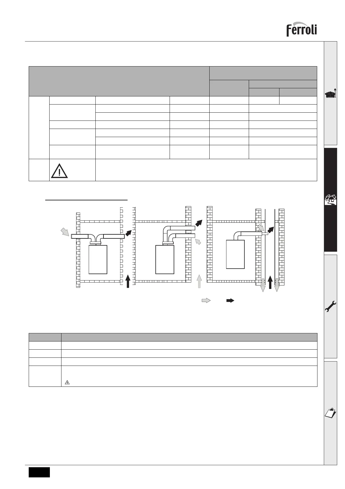
Connection to collective flues
fig. 27- Examples of connection to collective flues ( = Air / = Fumes)
Table. 6 - Examples & classification
If the boiler is to be connected BLUEHELIX TECH RRT 28 C to a collective flue or to a single flue with natural draught,
the flue or chimney must be expressly designed by professionally qualified technical personnel in conformity with the
current regulations and be suitable for room sealed fan assisted boilers.
Backflow preventer valve
The boiler BLUEHELIX TECH RRT 28 C is equipped as standard with a backflow preventer valve (anti-backflow sys-
tem), therefore it can be connected to a positivepressure collective flue system, only if using G20 gas.
Losses in m
eq
Air
intake
Fume exhaust
Vertical Horizontal
Ø 80
PIPE 1 m M/F 1KWMA83W 1.0 1.6 2.0
BEND 45° M/F 1KWMA65W 1.2 1.8
90° M/F 1KWMA01W 1.5 2.0
PIPE SECTION with test point 1KWMA70W 0.3 0.3
TERMINAL air, wall 1KWMA85A 2.0 -
fumes, wall with antiwind 1KWMA86A - 5.0
FLUE Fume outlet only Ø80 010036X0 +
1KWMA86U
-4.0
ATTENTION: CONSIDER THE HIGH PRESSURE LOSSES OF Ø50 and Ø60 ACCESSORIES; USE
THEM ONLY IF NECESSARY AND AT THE LAST FUME EXHAUST SECTION.
Type Description
C2X Intake and exhaust in common flue (intake and exhaust in same flue)
C4X Intake and exhaust in common and separate flues, but undergoing similar pressure zones
C8X Exhaust in single or common flue and wall air intake
B3X Intake from installation room by means of concentric duct (that encloses the exhaust) and exhaust in common flue with
natural draught
IMPORTANT- THE ROOM MUST BE PROVIDED WITH APPROPRIATE VENTILATION FOR COMBUSTION PURPOSES
 Loading...