Do you have a question about the Ferroli Bluehelix PRO C and is the answer not in the manual?
Emphasizes reading instructions, professional installation/maintenance, and safety during cleaning/faults.
Covers intended use, packaging hazards, user limitations, and proper disposal of the unit.
States manufacturer disclaimer for damages and notes potential differences in manual images.
Indicates heating demand via flashing hot air icon. Displays actual heating temperature and 'd2' during standby.
Indicates DHW demand via flashing hot water icon. Displays actual DHW temperature and 'd1' during standby.
Indicates comfort demand via flashing water icon. Displays actual water temperature in the boiler.
Displays fault code and 'd3'/'d4' messages during safety standby.
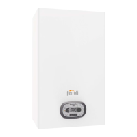
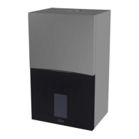
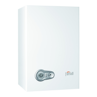
Introduces the BLUEHELIX PRO C as a high-efficiency condensing boiler for heating and DHW production.
Details the components and functions of the boiler's control panel.
Covers connecting power, switching the boiler on/off, and initial state.
Explains how to switch between Summer mode (DHW only) and Winter mode.
Details how to adjust the heating system temperature using control buttons.
Explains how to adjust the domestic hot water temperature using control buttons.
Describes setting room temperature via an optional room thermostat.
Explains setting room temperature using an optional remote timer control.
Covers the ECO and COMFORT modes for DHW delivery speed and user comfort.
Explains the 'Sliding Temperature' mode for automatic heating adjustment based on outside temperature.
Details how to adjust compensation curves and parallel curve offset for 'Sliding Temperature'.
Describes how adjustments are managed when a Remote Timer Control is connected.
Explains how to check and adjust the system water pressure and the air venting cycle.
Provides general guidelines and warnings for boiler installation by qualified personnel.
Covers requirements for the installation location, ventilation, and clearances.
Details safety valve outlet, system flushing, and relevant connections.
Ensures the unit is arranged for the correct fuel type and details connection requirements.
Covers earthing system requirements and mains connection with bipolar switch.
Important warning about connecting 230V to room thermostat terminals.
Explains how to access the electrical terminal block after removing the front panel.
Covers requirements for air inlet and fume outlet connection systems.
Details examples and typologies of coaxial pipe connections.
Illustrates starting accessories for coaxial duct connections.
Provides a table for maximum permissible lengths of coaxial pipes.
Details typologies and examples of connections with separate pipes.
Shows the starting accessory for separate duct connections.
Provides a table for maximum permissible lengths of separate ducts.
Lists accessories and their corresponding losses in mbar/m.
Explains how to connect the condensate drain and the importance of filling the trap.
Covers adjustments for gas conversion, TEST mode, and heating power.
Details the procedure for converting the boiler to operate on Natural Gas or LPG.
Explains how to activate TEST mode for boiler diagnostics and power adjustment.
Describes how to adjust the heating power using TEST mode.
Covers pre-startup checks and operational checks for safe boiler operation.
Lists essential checks before boiler ignition and during operation.
Provides step-by-step instructions on accessing the boiler's interior.
Explains how the boiler displays faults and identifies fault codes.
Lists fault codes, their causes, and recommended solutions for troubleshooting.
Diagram showing the main components and their identification numbers.
Diagram illustrating the boiler's internal hydraulic connections and components.
Provides detailed technical specifications for the boiler models.
Presents energy efficiency and performance data according to ErP regulations.
Presents energy efficiency and performance data according to ErP regulations.
Illustrates the electrical connections of the boiler's control system.
Explains the components and connections shown in the electrical wiring diagram.
| Type | Condensing Boiler |
|---|---|
| Fuel Type | Natural Gas / LPG |
| Efficiency Class | A |
| NOx Class | 5 |
| ErP Heating | A |
| ErP DHW | A |
| Heat Exchanger | Stainless Steel |
| Warranty | 2 years |
| Efficiency | Up to 98% |
| Control Panel | Digital |