BLUEHELIX TECH RRT 28 C
34 EN
cod. 354M1070 - Rev. 01 - 07/2018
Annual Boiler Service
To ensure the safe operation of the unit over time, a qualified Gas Safe registered engineer must carry out a yearly
inspection, and complete the following checks:
• The control and safety devices (gas valve, flow meter, thermostats, etc.) must operate correctly.
• The flue exhaust duct must be sealed.
• The boiler casing or chamber must be room sealed.
• The Flue terminal and ducts must be free of obstructions, leaks & located correctly to BS5440.
• The burner and exchanger must be clean and free of deposits. Use suitable soft brushes for cleaning. Never use
chemical products. (Wash down through the exchanger & out through the condense line with clean warm water).
• The electrode must be correctly positioned and free of scale.
The electrode can be cleaned of encrustation's only with a non-metallic brush, and must NOT be sanded.
• The gas and water systems must be tight.
• The water pressure in the system when cold must be approx. 1.5 bar; otherwise bring it to that value.
• The circulating pump must not be blocked.
• The expansion vessel must be charged to 1.0 bar with no system pressure.
• The gas flow and Inlet working pressure must match that given in the respective tables.
• The condense pipework must be solvent weld, sealed & free of debris or blockages.
• The condense trap must be full of water.
• Check the quality of the water in the heating system via an "alkalinity test" (checking the inhibitor concentration).
• Check the condition of the insulation within the exchanger & around the burner (Replace if cracked or damaged).
• Check the flexible gas connection between the valve and Venturi.
• Replace the burner gasket if damaged or over 5 years.
• Finally, always check the combustion parameters (see "checking the combustion values").
Replacement of major components & testing
After replacing the gas valve, burner, electrode or circuit board, it is necessary to carry out the 100% calibration (see
“100% calibration” on page 23). Then follow the instructions in par. “Checking the combustion values” on page 22.
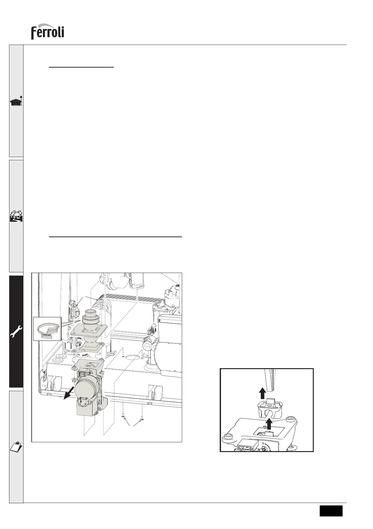
Gas valve
fig. 36- Gas valve replacement
• Disconnect the power supply and turn off the isola-
tion valve upstream of the gas valve.
• Disconnect the two electrical connectors to the gas
valve
• Disconnect the gas supply pipe to the gas valve
• Undo the screws “1”
• Remove the clamp “2”
• Remove the gas valve “3”
• Then undo the screws “4”
• Fit the new valve, carrying out the above steps in
reverse order.
Refer to the instruction sheet included in the kit
when replacing the gas Injector cartridge..
fig. 37- Gas Injector cartridge replacement
1
4
2
3

 Loading...