
L
Lisa ChambersSep 23, 2025
What does Error 25 mean on a Ferrotec Controller?
- KKayla ThomasSep 23, 2025
Error 25 on the Ferrotec Controller indicates an RS-232 Error.
What does Error 25 mean on a Ferrotec Controller?
Error 25 on the Ferrotec Controller indicates an RS-232 Error.
What does it mean when my ferrotec genius shows Error 06?
If your Ferrotec Controller shows Error 06, it means the voltage undercuts the set point by more than 500 V.
What does Error 14 mean on the ferrotec genius Controller?
Error 14 on the Ferrotec Controller means there is no communication to the slave unit.
What does Error 15 mean on the Ferrotec Controller?
Error 15 on the Ferrotec Controller indicates that there is no communication to the master unit.
Why does my ferrotec genius show Error 18?
Error 18 on the Ferrotec Controller indicates that the ADC Converter for FPS II is out of limits. Possible reasons are a broken filament, fiber optics not in place, emission current too high, or ADC power failure.
What does it mean when my ferrotec genius Controller shows Error 20?
If your Ferrotec Controller displays Error 20, it indicates that the system setup has been changed; you should check system constants.
What does Warning 11 mean on a ferrotec genius Controller?
Warning 11 on the Ferrotec Controller indicates that the memory is full in GENIUS, and data was not saved.
What does Warning 12 mean on a ferrotec genius Controller?
Warning 12 on the Ferrotec Controller means that the data is already active and cannot be deleted.
What does Error 08 mean on the ferrotec genius Controller?
Error 08 on the Ferrotec Controller means that the data set is non-existent, and default data has been loaded.
What does Error 04 mean on a Ferrotec Controller?
Error 04 on the Ferrotec Controller means that the WATER interlock is open for more than 3 seconds. This indicates an open contact or no voltage between contact A1 and B1 on X110 (factory setting).
Specifies the authorized use and limitations of the controller.
Explains different types of safety warnings and symbols.
Defines common safety symbols used in the manual.
Describes the built-in safety mechanisms of the controller.
Explains the function and testing of the emergency stop.
Warns about specific dangers within the operational zone.
Defines operational zones and potential hazard areas.
Step-by-step instructions for safely powering down the unit.
Details on wiring the controller to other system components.
Provides a visual representation of the electrical connections.
Instructions for proper safety grounding.
Specific steps for connecting the controller.
Steps for initial setup, connection, and checks.
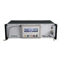
Overview of the control panel and its components.
How to use the left joystick for menu selection.
How to use the right joystick to modify values.
Detailed explanation of the LCD screen and its sections.
Procedure for adjusting the emission current.
Adjusting magnet current for beam deflection.
Setting the magnet current's position.
Setting the magnet current's amplitude.
Basic principles of menu navigation.
How to set and adjust evaporation parameters.
Adjusting the magnet current's beam position.
Defining the operational limits for magnet current.
Adjusting the magnet current's beam amplitude.
Adjusting the high voltage output level.
Setting the maximum allowable emission current.
Setting the frequency of magnet current deflection.
Accessing and using service functions.
Explanation and handling of system error messages.
Explanation and handling of system warnings.
Pinout and configuration for the X110 I/O interface.
Control logic for the High Voltage power supply.
Configuration options for different sweep modes.
Utilizing dwell matrix patterns for energy distribution.
| Brand | ferrotec |
|---|---|
| Model | genius |
| Category | Controller |
| Language | English |