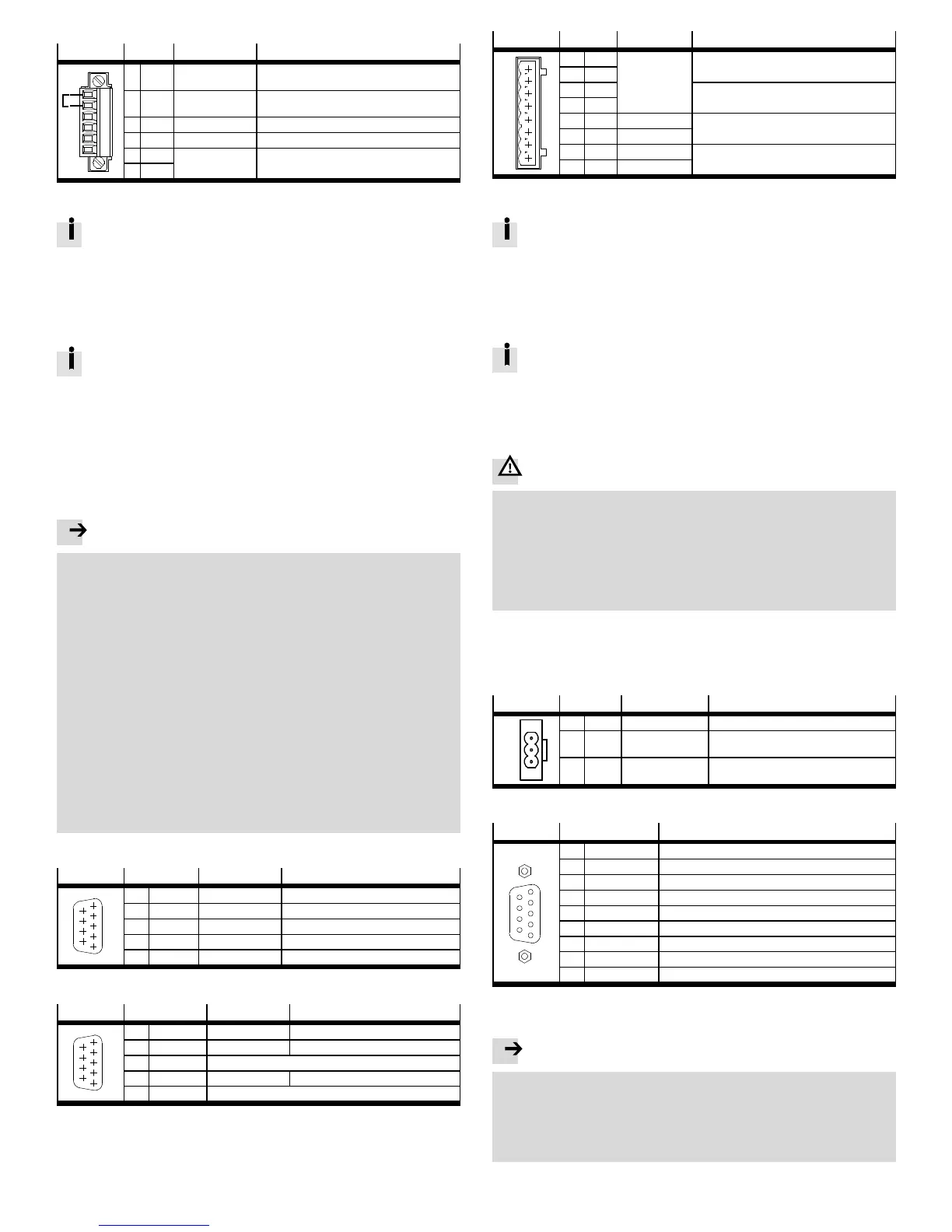
4.3 STO interface [X3]
Interface [X3] (Circuitry without use of the STO safety function)
[X3]
Pin Value Description
1
2
3
4
5
6
1 24 V 24 V DC Voltage o utput (24 V DC lo gic supply carried
out as auxiliary vo ltage)
2 REL 0V/24VDC Setting and resetting the relay for interrupting
the driver supply
3 0V 0V(GND24VDC) Reference potential for PLC (24 V DC)
4 – – –
5 NC1 Max. 25 V AC,
30 V DC, 2 A
Potential-free feedback contact for driver supply,
N/C contact
6 NC2
Circuitry without use of the STO safety function
If you do not need the integrated safety function STO in your application,
to operate the motor c ontroller you must bridge Pin 1 and Pin 2 at the X3
interface (delivery status).
This deactivates the integrated safety function!
With this circuitry, safety in the application must be ensured through other
appropriate measures.
Use of the STO safety function
For intended use of the safety function STO – “Safe Torque Off ”, observe
the information in the STO description GDCP-CMMS-ST-G2-S1-...
Use the “Safe torque off ” function (STO) whenever you have to reliably disconnect
the energy supply to the motor in your application. To ensure the function STO
“Safe Torque Off ”, the control ports DIN4 [X1.21] and Rel [X3.2] must be connec-
ted in two channels through parallel wiring. This interface can be part of an emer-
gency stop circuit or a protective door arrangement, for example.
Recommendation for first commissioning without safety engineering:
Minimum circuitry with emergency stop switching device and two-channel switch-
off via the control por ts REL [X3.2] and DIN4 [X1.21].
Note
Loss of the safety function.
Lack of the safety function can result in serious, irreversible injuries, e.g. due to
uncontrolled movements of the connected actuator technology.
– The STO function request must always run over X3.2 a nd X1.21 (end stage
enable).
– If uncontrolled coasting can result in a hazard or damage, additional meas-
ures are required.
– A clamping unit is actuated by the non-safety-relevant firmware of the CMMS-
ST-...-G2 motor c ontroller.
• Make sure that no jumpers or the like can be inserted parallel to the safety
wiring, e.g. through the use of the maximum wire cross section of 1.5 mm² or
suitable wire end sleeves with insulating collars.
• Use twin wire end sleeves for looping through lines between neighbouring
devices.
• Comply with the specified environmental and connection conditions, in partic-
ular the input voltage tolerances.
• Place the motor controller in operation only if all safeguarding, including the
safety function, has been installed and checked.
• The safety function must be checked and, prior to the intended use, a corres-
ponding validation must be carried out.
4.4 CAN [X4]
[X4]
Pin Value Description
5
1
2
3
4
6
7
8
9
2 CANL 5V,Ri=60Ω CAN low, signal line
3 GND – CAN GND, not galvanically isolated
5 Screening – Connection for th e cable screening
6 GND – CAN GND, not galvanically isolated
7 CANH 5V,Ri=60Ω CAN high signal line
4.5 Serial interface RS232/RS485 [X5]
[X5] RS232
Pin
1)
Value Description
5
1
2
3
4
6
7
8
9
2 RS232_RxD 10 V, Ri > 2kΩ Receive signal
3 RS232_TxD 10 V, Ra < 2kΩ Transmission signal
4 RS485_A Positive transmission and reception signal
5 GND 0V Reference potential 0 V DC
9 RS485_B Negative transmission and reception signal
1) Connect only the pins for RS232 or RS485, dependent on the interface used!
4.6 Motor [X6]
[X6]
Pin Value Description
1
2
3
4
5
6
7
8
1 A 4x0…58V
Max. 12 A
eff
Connection power train A
2 A/
3 B Connection power train B
4 B/
5 T+ +3.3V,5mA Temperature sensor (N/C contact, N/O contact /
PTC o r KTY)
6 T- 0V
7 BR+ 24 V Motor holding brake
1)
8 BR- 0V
1) In the motor and connecting cable, reliable separation of the motor temperature sensor from the motor
circuit must be ensured.
If third-party cables are used: Place the co mplete screening of the motor-
side cable flat on the plug or motor housing. Length ≤ 40 mm.
• Place the complete screening of the motor c able at the screening con-
nection terminal of the related motor c ontroller so that the leaked cur-
rent can flow back into the controller that causes the leak
• Do not use the complete screening as strain relief
Connection of a holding br ake
Holding brakes are not appropriate for braking the motor. They only serve
functional holding of the motor shaft. Additional measures are required for
use in safety-oriented applications.
4.7 Power supply [X9]
Protection against electric shock through protective extra-low voltage (PELV):
Warning
Danger of electric shock
• For the electric logic supply and electric load voltage, use only PELV circuits in
accordance with EN 60204-1 (Protective Extra-Low Voltage, PELV). Also take
into account the general requirements for PELV circuits in accordance with
EN 60204-1.
• Make sure that the reference potential of the logic and load supply is connec-
ted to FE at a cen tral position .
• Use only voltage sources that ensure a reliable electric separation of operat-
ing voltage in accordance with E N 60204-1.
Through the use of PELV circuits, protection from electric shock (protection from
direct and indirect contact) in acc ordance with EN 60204-1 is ensured (Electrical
equipment of machines. General requirements). A 24 V power supply unit used in
the system must satisfy the requirements of EN 60204-1 for DC power supply ( be-
haviour during power interruptions, etc.).
[X9]
Pin Value Description
IC+
24 V
0V
1 IC+ 12 V DC … 58 V DC Intermediate circuit voltage
2 24 V 24 V DC _20 % Supply o f the control section
3 0V - Common reference potential for the
intermediate ci rcuit and control section
4.8 Master/slave interface [X10]
[X10]
Pin Description
6
7
8
9
2
1
3
4
5
1 A/CLK/CW Tracking signal A/pulse CLK/steps CW
2 B/DIR/CCW Tracking signal B/direction DIR/steps CCW
3 N Incremental encoder zero pulse N
4 GND
1)
Reference GND for incremental encoder
5 VCC Auxiliary supply, maximum load 100 mA
6 #A/#CLK/#CW Tracking signal A/pulse CLK/steps clockwise CW
7 #B/#DIR/#CCW Tracking signal B/direction DIR/steps CCW
8 #N Zero pulse N
9 GND
1)
Screening for the connecting cable
1) Pin 4 and pin 9 are connected internally
5 Commissioning
Note
Danger from unexpected movement of the motor or axis
• Make sure that the movement does not endanger anyone.
• Parameterise the motor controller with the Festo Configuration Tool (FCT)
before enabling the controller via DIN5 [X1.9].
– Bypassing of safety equipment is impermissible
Recommendation for first c ommissioning without safety equipment
Section 4.3

 Loading...


