2 Description of the safety function STO
Festo – GDCP-CMMS-ST-G2-S1-EN – 1404NH – English 15
2.2.2 Overview of interfaces [X1] and [X3]
The motor c ontroller has control ports for requesting the safety function at the following interfaces
Section 3.2:
– 25-pin c onnection [X1] on the top side with the c ontrol port (1st switch-off path) and the controller
enable control port (for implementation of the SS1 function in combination with an externally safe
time relay).
– 6-pin c onnection [X3] on the bottom with a c ontrol port (2nd switch-off path), an ac knowledgment
contact and a 24 V auxiliary supply for external sensors.
A safety c ircuit for additional interfaces on the CMMS -ST-...-G2 motor controller is neither required nor
intended.
Tab. A.6 in appendix A.1.3 describes the tec hnical data for the control ports.
Cross-circuit detection in the input circuit is not c arried out by the motor c ontroller.
The inputs have no tolerance against test pulses (OSSD).
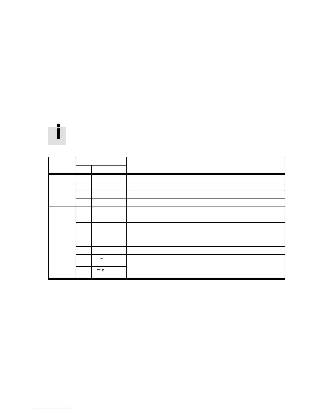
Interface
Port Description
Pin Designation
[X1] 6 GND24 Reference potential for digital inputs and outputs
9 DI N5 Controller enable (high active)
18 +24 V 24 V supply provided
21 DIN4 Output stage enable (high active)
[X3] 1 24 V Auxiliary power supply (24 V DC logic supply of the motor control-
ler provided).
2 Rel Activation of driver supply relay
High = driver supply switched on
Low = “pulse blocker” active, driver supply switched off
3 0V Reference potential for digital inputs and outputs.
5 1(NC1)Acknowledgment contact for the status “Safe Torque Off ” (S TO)
– Acknowledgment contact closed = “Safe Torque Off” (STO)
active (or controller switched off )
6 2(NC2)
Tab. 2.2 Function of the connections
For STO in category 3‚ PL d in ac c ordance with EN IS O 13849-1, two c hannels are required, that is, an
unintended restart must be reliably prevented through two separate paths that are completely inde-
pendent of each other. The se two path s for interrupting the energy supply to the drive wit h the reliable
impulse block are called switch-off paths:
1st switch-off path:
Output stage enable via [X1] (blocking of the PWM signals; the MOSFET drivers are no longer actuated
with pulse patterns).
2nd switch-off path:
Interruption o f th e supply for the eight drivers for the end stage MOSFETs via [X3] using a relay (th e
MOSFET drivers are separated from the power supply via a relay, thus preventing the PWM signals from
reaching the MOSF ETs).

 Loading...


