2 Product overview
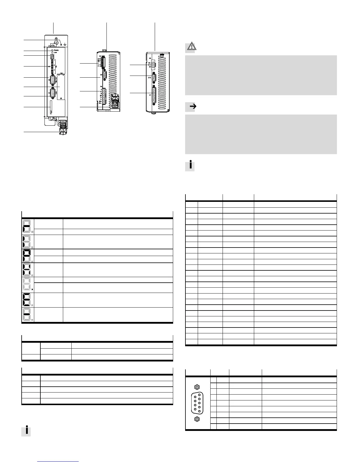
2.1 Device view
123
4
5
6
7
8
9
aJ
aA
aB
aC
aD
aE
aF
aG
aH
aE
1 Front view
2 View underneath
3 View on top
4 Earthing screw (central FU
connection)
5 LED status display
6 7-segments display
7 [S1]: DIP switch
8 [X5]: RS232/RS485
9 [EXT]: Slot for CAMC-...
aJ [X4]: CAN bus
aA [ M1]: SD memory card
aB [ X3] STO interface
aC [ X2] Encoder
aD [ X6] Motor
aE Shield connection terminal
aF [X9] Power supply
aG [ X10] Master/slave
aH [ X1] I/O interface
Fig. 1 Motor controller CMMS-ST-...-G2
2.2 Display and control elements
7-segments display
1)
Rotating out-
side segments
Speed mode (speed adjustment):
Display changes corresponding to rotor position and speed.
Middle segment Controller enable active (motor is energised).
I Force mode (current control).
Pxxx Positioning mode, record number x x x
PHx Homing phase x
H Two-channel safety function requested (DIN4 [X1.21] and Rel [X3.2]).
POINT Start program (Bootloader) active.
Flashing point – Firmware file (memory card) is being read.
– Display of errors th rough the start program.
Exxy Error (E = error)
Number: Two -position main index (x x), single-position subindex (y )
Example: E 0 1 0 Section 7.
–xxy– Warning
Number: Two -position main index (x x), single-position subindex (y ).
Example:-170- Section 7.
1) Several characters are displayed one after the other.
LED display
Ready Green Operating status/controller enable
Flashing green Parameter file (memory card) is being read/written
CAN Yellow Status display: CAN bus active
DIL switch
S1.1 … 7 CAN bus address o r MAC-ID
S1.8 Automatic loading of new firmware from memory card
S1.9 … 10 Setting th e CAN-bus transmission rate
S1.11 Activatio n of the CAN-bus interface
S1.12 Terminating resistor for CAN-bus
3 Mechanical installation
3.1 Mounting
Observe the information on the installation dimension s and free spaces in
the Mounting and installation description GDCP-CMMS-ST-G2 -HW-. ..
For vertical mounting onto a control cabinet mounting plate:
• Use the motor controller exclusively in a control cabinet:
– mounting position vertical with the power supply lines [X9] on top
– attachment to the mounting holes with two M4 screws.
4 Electrical installation
Caution
Danger from unexpected movement
Faulty pre-assembled lines may destroy the electronics and trigger unexpected
movements of the motor.
• When wiring the system, use only the supplied plug connectors and preferably
the cables listed in the catalogue as accessories.
www.festo.com/catalogue
• Lay all flexible lines so that they are free of kinks and free of mechanical
stress; if necessary in an energy chain.
Note
ESD (electrostatic discharge) can cause damage to the device or other system
parts at plug connectors that are not used.
• Before installation: Earth the system parts and use appropriate ESD equip-
ment (e.g. shoes, earthing straps etc .).
• After installation: Seal unassigned D-sub plug connectors with protective caps
(available at authorized dealers).
• Observe the handling specifications for electrostatically sensitive devices.
Observe the information on safe and EMC-suitable installation and on
protective earthing in the mounting and installation description, G DCP-
CMMS-ST-G2-HW-....
4.1 I/O interface [X1]
Pin
Value Assignment in 0 mode – positioning
1 SGND 0V Screening for analogue signals
2 DIN12/AIN0 –/max. 30 V Mode bit 0/setpoint input 0
2)
3 DIN10 – Record selection bit 4 (high active)
4 +VREF +10V ±4 % Reference output for setpoint value potentiometer
5 – – –
6 GND24 – Reference po tential for digital I/O modules
7 DIN1 – Record selection bit 1 (h igh active)
8 DIN3 – Record selection bit 3 (h igh active)
9 DIN5 – Controller enable (high active)
10 DIN7 – Limit switch 1
11 DIN9 – Mode bit 1
12 DOUT1 24 V 100 mA Motion complete (h igh active)
1)
13 DOUT3 24 V 100 mA Common error (low active)
1)
14 AGND 0V Reference potential for analogue signals
15 DIN13/#AIN0 –/Ri = 20 kΩ Stop (lo w active)/reference potential AIN0
2)
16 DIN11 – Record selection bit 5 (h igh active)
2)
17 AMON0 0…10V±4% Output: analogue monitor 0
18 +24VDC 24 V 100 mA Output: 24 V DC, looped through from [X9.6]
19 DIN0 – Record selection bit 0 (h igh active)
20 DIN2 – Record selection bit 2 (h igh active)
21 DIN4 – Output stage enable (high active)
22 DIN6 – Limit switch 0
23 DIN8 – Start for the positioning procedure (high active)
24 DOUT0 24 V 100 mA Output: Controller ready for operation (high active)
25 DOUT2 24 V 100 mA Start acknowledged (low active)
1)
1) Default setting, configurable in the Festo Configuration Tool (FCT).
2) Pin allo cation with control via analogue input
4.2 Encoder [X2]
[X2]
Pin Value
1)
Description
6
7
8
9
2
1
3
4
5
1 A+ 5 V , Ri = 120 Ohm Increment generator signal A, po sitive polarity
2 B+ 5 V , Ri = 120 Ohm Increment generator signal B, positive polarity
3 N+ 5 V , Ri = 120 Ohm Zero pulse N, positive polarity
4 GND - Reference GND for the encoder
5 VCC +5 V +-5 % 100 mA Auxiliary supply, max. 100 mA
6 A- 5 V , Ri = 120 Ohm Increment generator signal A, negative polarity
7 B- 5 V, Ri = 120 Ohm Increment generator signal B, negative polarity
8 N- 5 V, Ri = 120 Ohm Zero pulse N, negative polarity
9 GND - Internal screen for the connecting cable
1) R
i=
Internal resistance
 Loading...


