Note
Damage to the motor controller
The motor c ontroller is damaged in case of
– excessive operating voltage
– polarity reversal of the operating voltage connections
– interchange of operating voltage and motor c onnections
– shor t circuits in the motor circuit between the motor phases and FU
• Comply with the specified values for the supply voltage .
• Before switching on, chec k the connections [X9] and [X6].
• Check to ensure there is no FU short in the motor connection circuit.
Before switching on the power supply:
Check the installation of the motor controller:
• Check all connections.
• Connect all FU conductors, even for brief measuring and test purposes.
• Mounted module or cover plate on the card slot [EXT]. Mounted line on [X9]
and [X6].
Checking ready status
1. Make sure that the controller enable is switched off ( c ontroller enable: DI N 5
[X1.9] ).
2. Switch on the power supplies of all devices. The READY LED on the front of the
device should now light up.
If the READY LED is not lit, there is a malfunction. If an “E” appears in the 7-seg-
ments display followed by a sequence of numbers, this is an error message and
you must eliminate the cause of the error.
Additional steps for preparation of commissioning can be found in the
Function description GDCP-CMMS-ST-G2-FW- ...
6 Obligations of the operator for the safety function
The operational capability of the safety device is to be checked at adequate interv als. It
is the respon sibility of the operator to choose the ty pe of check and tim e in tervals in
the specifi ed ti me per iod . The check is to be condu cted so the excell en t functionin g of
the safety device in interacti on with all the com pon en ts can be veri fi ed.
Recommendation: Carry out a performance test at least every 24 hours.
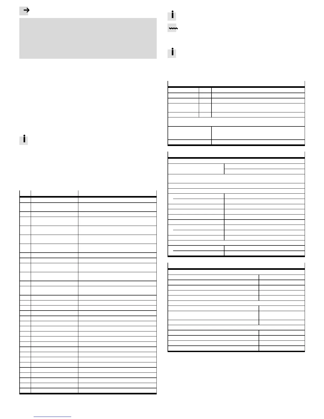
7 Diagnostics and fault clearance
No.
Message group Cause/measure
01-x Internal error – stack overflow Load approved firmware.
02-x Undervoltage in intermediate
circuit
Check power supply, intermediate circuit v o ltage,
undervoltage monitoring (threshold value).
03-x Temperature monitoring, motor Check parameterisation (current regulator, limits).
04-x Temperature monitoring,
electronics
Check installation conditions and cylinder sizing.
05-x Internal po wer supply Check 24 V logic supply. If error is present witho ut
connected peripheral equipment Repair.
06-x Intermediate circuit
(over-current)
Check motor, cable and motor controller.
07-x Intermediate circuit
(over v o ltage)
Check design and connection of the braking resistor.
08-x Angle encoder Check encoder and encoder signals.
11-x Homing Check ho ming, switch arrangement.
12-x CAN Re-start CAN controller. Ch eck CAN configuration in th e
controller. Check wiring.
14-x Motor identification Check intermediate circuit voltage, encoder cable.
Motor blocked, e.g. ho lding brake does not release?
16-x Initialization Load fi rmware again. Hardware defective?
17-x Following error monitoring Increase error window. Parameterise accel eration to
be less. M o to r ov erloaded?
18-x Temperature monitoring Ch eck installation conditions.
19-x I²t monitoring Motor/mechanics blo cked or sluggish?
21-x Current measurement If the error occurs repeatedly Hardware defective.
22-x PROFIBUS Check slave address, bus termination, cabling.
25-x Firmware Update th e firmware.
26-x Data flash Load factory setting. Hardware defective?
29-x SD card Check SD card.
31-x I²t monitoring Check motor and mechanical system.
32-x Intermediate circuit Check mains v o ltage/power supply, braking resistor.
35-x Fast stop Check parameterisation.
40-x Software limit Check target data and po sitioning range.
41-x Path program Check parameterisation.
42-x Positioning Parameterisation/sequence control, homing?
43-x Limit switch error Check parametrisation, wiring and limit switches.
45-x STO error Check activation; the error must no t recur.
64-x DeviceNet error Check configuration and network.
65-x Dev iceNet error Check configuration and network.
70-x Operating mode error Check factor group and impermissible change.
79-x RS232 error Check wiring and transferred data.
8 Repair and disposal
Repair or maintenance of the motor c ontroller is not permissible. If re-
quired, replace the motor controller.
Observe the local regulations for environmentally friendly disposal of elec-
tronic c omponents.
9Technicaldata
The complete technical data on CMMS-ST-...-G2 Mounting and installa-
tion description GDCP-CMMS-ST-G2-HW-....
When using the safety function, observe the special technical data and
restrictions on environmental conditions in dependence on required out-
put nominal power in the description STO GDCP-CMMS-ST-G2-S1 -...
Safety reference data and safety specifications
Safety function STO STO, Safe T orque Off
Category 3 Grading in categories in accordance with EN ISO 13849-1
Performance Level PL d Performance level in accordance with EN ISO 13849-1
T [Years] 20 Proo f test interval
Duration of use in accordance with EN ISO 13849-1
MTTF
d
[Years] 2521 Mean time to dangerous failure.
Due to the ser vice life of the internal switching relay, the safety data for the STO function apply
for an annual actuation rate of nop = 500,000 / a (CMMS-ST-...-G2 from Rev. 02).
Type test The functional safety engineering o f the product has been
certified by an independent testing auth o rity (cer tificate
www.festo.com/sp).
Reliable component yes, for the STO safety function
General technical data
Product conformity and certifications
CE marking (declaration o f conformity
www.festo.com/sp)
in accordance with EU Machinery Directive 2006/42/EC
In accordance with EU EMC Directive 2004/108/EC
The dev ice is intended for use in an industrial environment. Measures for interference suppression
may need to be implemented in residential areas.
Operating and environmental conditions
Permissible setup altitude above sea level
with nominal power [m] 1000
with power reduction [m] 1000 … 3000
Air humidity [%] 0 … 90 (non-condensing)
Degree of protection IP20
Degree of contamination 2
Ambient temperature
with nominal power [°C] 0…+40
with power reduction [°C] +40 … +50
Storage temperature [°C] –25 … +70
Vibration and resistance to shocks
Operation in accordance with EN 61800-5-1, section 5.2.6.4
Conveying in accordance with EN 61800-2, section 4.3.3
Power supply/braking resistor [X9]
Load voltage
Nominal voltage, lo ad v o ltage supply [V DC] 48
Alternative load voltage supply (parameterisable) [V DC] 24, 48
Voltage range [V DC] 12 … 58
Nominal current [A] 8 (with nominal motor current)
PWM switching frequency (permanently set) [kHz] 50
Logic supply
Nominal voltage [V DC] 24 ± 20 %
Nominal current (outputs unloaded, without ho lding
brake)
[A] 0.2
Maximum current (incl. holding brake) [A] 1.5
Integrated braking resistor
Braking resistor [Ω] 17
Pulse power (for 50 ms) [W] 500
Nominal power [W] 10
Rated trigger level [V DC] Adjustable in FCT up to 58
 Loading...


