EasyManua.ls Logo

Festo CPV10-GE-DI01-8 - User Manual

Festo CPV10-GE-DI01-8
54 pages
Print Icon
To Next Page IconTo Next Page
Loading...
CPV10/14-GE-DI01-8
Electrical interface
8160540
2022-03e
[8160542]

Table of Contents

Other manuals for Festo CPV10-GE-DI01-8

Question and Answer IconNeed help?

Do you have a question about the Festo CPV10-GE-DI01-8 and is the answer not in the manual?

Summary

About This Document

Applicable Documents

Lists related technical documentation for the product.

Product Version Information

Details specific software and hardware versions covered by this manual.

Safety and Product Overview

Safety Instructions

Essential guidelines for safe operation and handling of the product.

Intended Use and Personnel Training

Defines the product's application scope and required personnel qualifications.

Product Design Overview

Product Component Identification

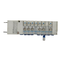
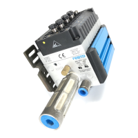
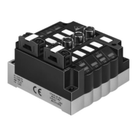
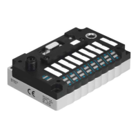
Diagram illustrating key parts of the CPV valve terminal.

Product Design Details

LED Display Elements for Status

Explains the function of various LEDs indicating operational status.

Control Elements: DIL Switches & SAVE Button

Describes the function of DIP switches and the SAVE button for configuration.

Connecting Elements and Interfaces

Power Supply and Fieldbus Interfaces

Details pin assignments for power and PROFIBUS DP connections.

CPI Expansion Port Functionality

Describes the port for connecting additional CPI/CP modules.

Installation: Initial Setup

Settings and Switch Cover Removal;Installation

Procedure for accessing and interacting with control elements.

Installation Settings and Configuration

PROFIBUS Address and Diagnostic Mode Setup

Guides on setting the PROFIBUS address and diagnostic mode.

CPI Extension Detection via SAVE Button

Procedure for automatically detecting connected CPI/CP modules.

Fieldbus Connection: Cable Requirements

Fieldbus Cable Specifications

Defines the electrical characteristics for the fieldbus cable.

Fieldbus Connection Parameters

Baud Rate, Length, and Connection Options

Covers transmission speed, bus length limits, and connection methods.

Fieldbus Connection Options

Bus Terminal and M12 Adapter Connections

Instructions for bus termination and M12 adapter connections.

Power Supply Installation Procedure

Power Supply Cables and Assembly Guide

Details selecting and connecting power supply cables.

Power Supply Selection Criteria

Selecting the Appropriate Power Pack

Guidance on choosing a power supply based on system consumption.

Power Supply Connection and Safety

Connecting Load Voltage and Safety Measures

Steps for connecting load voltage and crucial safety precautions.

Equipotential Bonding for Interference Reduction

Grounding Connections for Electromagnetic Compatibility

Ensures proper grounding to prevent interference.

System Expansion: Connecting Modules

Extending the CPV Master with CPI;CP Modules

Rules and guidelines for expanding the system.

System Preparation for Commissioning

CPI String Checks and Assignment Saving

Procedures for verifying and saving the CPI system configuration.

System Operation and Behavior

Switch-on Behavior and String Assignment Verification

Describes system response upon power-up and assignment matching.

Commissioning and Malfunction Handling

Malfunction Behavior and Error Elimination

How the system behaves during malfunctions and how to fix errors.

Commissioning: Address Management

CPV Master and CPI;CP Module Address Assignment

Details on assigning addresses to system components.

Commissioning: Software Configuration

Device Master Files and Siemens Configuration

Information on GSD files and configuring with Siemens STEP 7.

Commissioning: PROFIBUS DP Integration

DP Master Commissioning Steps and Examples

Guides for commissioning a general DP master with configuration examples.

Diagnostics: LED Status Indicators

Interpreting LED Displays for System Status

Explains normal and error states indicated by product LEDs.

Diagnostics: PROFIBUS DP Communication

Diagnostic Words, Steps, and Data Overview

Details on PROFIBUS DP diagnostic data structure and interpretation.

Error Handling and Controller Responses

Malfunction Behavior and SIMATIC S7 Error Management

Describes system responses to errors and integration with Siemens controllers.

Online Diagnostics Using STEP 7 Software

Reading Diagnostic Buffers and Module Information

Procedures for accessing diagnostic data through STEP 7.

Fault Diagnosis: Short Circuits and Overloads

Handling Output Module and Sensor Supply Faults

Steps to diagnose and clear short circuit or overload conditions.

Technical Data: General and Electrical Specs

General Environmental, Operating Voltage, and Current Data

Covers operating conditions, voltage, and current ratings.

Technical Data: System and Communication Specs

CPI System Parameters and PROFIBUS DP Data

Details on system limits, update times, and PROFIBUS DP communication rates.

Festo CPV10-GE-DI01-8 Specifications

General IconGeneral
BrandFesto
ModelCPV10-GE-DI01-8
CategoryTouch terminals
LanguageEnglish

Related product manuals