Do you have a question about the Festo SDE5-D10-FP-Q6E-P-M8 and is the answer not in the manual?
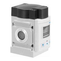
| Product Name | SDE5-D10-FP-Q6E-P-M8 |
|---|---|
| Category | Accessories |
| Manufacturer | Festo |
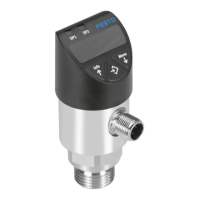
| Connection | M8 |
| Type | Pressure Sensor |
| Series | SDE5 |
| Port Size | Q6E |
| Electrical Connection | M8 Connector |
| Pressure Range | 0 ... 10 bar |
| Switching output | PNP |
| Type of pressure | Relative pressure |
| Protection class | IP65 |
| Operating voltage range DC | 15 to 30 V DC |
| Measuring range | 0 to 10 bar |
| Operating medium | Compressed air, inert gases |
| Medium temperature | 0...60 °C |
| Ambient temperature | 0...60 °C |
| Materials in contact with medium | Stainless steel |
Illustrates signal curves for different switching functions (NO/NC) and operational modes.
Explains threshold value comparison for Mode 0 (NO/NC) operation.
Explains threshold value comparison for Mode 1 (NO/NC) operation.
Explains hysteresis comparison for Mode 2 (NO/NC) operation.
Explains window comparison for Mode 3 (NO/NC) operation.
Provides essential conditions for correct and safe product use at all times.
Instructions for fitting the sensor's mechanical parts and wall supports.
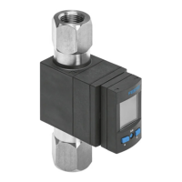
Details connecting pneumatic ports and lists tubing variants.
Warns about using power units with reliable electrical isolation per standards.
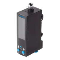
Details pin assignments, cable colors, and plug configurations for electrical connection.
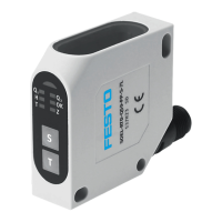
Step-by-step guide to setting switching pressure on O/C models using the EDIT button.
Guide for setting switching pressures using two teach pressures on specific models.
Guide to selecting operating modes 1-3 on FP models using the EDIT button.
Explains how teach pressure sequence (TP1, TP2) defines NO/NC function.
Warns about overheating due to high pressure and pulse frequencies.
Troubleshooting steps for when the LED display is not functioning.
Troubleshooting for incorrect sensor reaction or output.
Specifies rated and brief overload pressure ranges for different models.