Do you have a question about the Festo SFAM-62 and is the answer not in the manual?
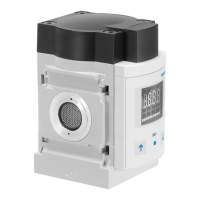
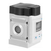
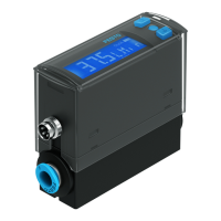
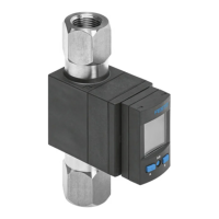
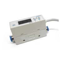
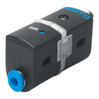
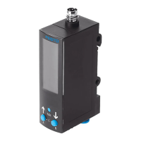
Provides an overview of the SFAM flow sensor and its components.
Describes the thermal measurement principle, outputs, and application of the SFAM flow sensor.
Important warnings and precautions for safe product operation and handling.
Details the mechanical mounting instructions for the SFAM flow sensor.
Specifies the requirements for pneumatic connections to ensure accuracy.
Outlines the electrical wiring, voltage, and connection requirements for the SFAM.
Instructions for combining the SFAM with MS series service units.
Guides through the initial steps for commissioning the SFAM device.
Details setting switching points and hysteresis for flow measurement outputs.
Explains the various symbols used on the SFAM display.
Lists the essential steps and checks before commissioning the SFAM.
Illustrates symbols used for navigating the SFAM's menu structure.
Describes the normal operating mode, displaying measurement values and signal states.
Explains how to view current settings for switching outputs.
Details configurable settings for Output A, including flow or consumption measurement.
Details configurable settings for Output B, including flow and display color change.
Configures the switching function for flow measurement on outputs.
Configures the switching function for air consumption measurement.
Configures the display color change feature for Output B.
Accesses advanced settings like standard conditions, units, filters, and security.
Configures standard conditions for accurate air mass flow measurement.
Selects the desired physical unit for flow measurement (l/min or scfm).
Adjusts filter time constants for the analogue output signal.
Configures digital filter steps for display smoothing.
Configures switching outputs as PNP or NPN.
Sets a numerical code to protect settings from unauthorized access.
Guides on teaching switching points for threshold or window comparator modes.
Details teaching the switching point for threshold comparison.
Details teaching switching points for window comparison.
Performs manual accumulated air consumption measurement.
Resets the accumulated measurement value to zero.
Crucial notes on operation, heat, and comparing volume flows.
Step-by-step guide to reset the SFAM to its factory default settings.
Lists malfunctions, possible causes, and remedies for SFAM issues.
Covers general info, materials, mounting, and pneumatic connection specs.
Details input signals, switching/analogue outputs, electronics, and electrical connections.
The SFAM-62 is a flow sensor designed for monitoring changes in flow and air consumption within industrial pipe systems or end devices. It can operate autonomously (SFAM-...-T) or be integrated with MS series service units (SFAM-...-M). The measurement principle is thermal, calculating the amount of heat drawn from a heated sensor surface by the flowing medium to determine flow or accumulated air consumption, which is then shown on a display.
The SFAM-62 provides two binary outputs (Out A/B) and one analog output (Out C) for connection to higher-level systems. Switching points can be configured for both binary outputs. For flow measurement, switching points are available for both binary outputs. For accumulated air consumption measurement, a consumption switch impulse is provided for output A (Out A). A combination of accumulated air consumption measurement (Out A) and flow measurement (Out B) is also possible. The flow rate value is transmitted via the analog output.
The device offers various display modes and settings. In RUN mode, it displays current measurement values for flow (l/min or scfm) and air consumption (m³, scf, or l), along with the signal states of the switch outputs (set or not set). A flashing value indicates that the measurement is outside the permissible range.
The SHOW mode allows users to view the current settings for switching outputs Out A and Out B. Pressing the A or B button initiates SHOW mode for the respective output. Repeated presses cycle through the settings. If faults are present, corresponding fault numbers are displayed first. After all settings are shown, the SFAM returns to RUN mode, displaying the current measurement value. This mode also facilitates switching between displayed measurement values, such as combining air consumption and flow measurements.
The EDIT mode enables comprehensive configuration of the device. Settings include:
To enter EDIT mode, the Edit button must be pressed for 3 seconds. If a security lock is active, the code must be entered first. The binary outputs can be wired as PNP or NPN connections, and this configuration must be matched in the special menu.
The TEACH mode allows for teaching switching points. This process involves generating a flow (Flow 1), pressing the A button and Edit button to record the first Teach point, generating a second flow (Flow 2), and then pressing the A button and Edit button again to record the second Teach point. The switching points (SP or SP.Lo/SP.Hi) are then set based on these taught values. If security blocking is active, the security code must be entered before teaching.
The RECORDER mode enables manual accumulated air consumption measurement. Pressing the A and B buttons simultaneously toggles between [Run] and [Stop] status. When [Run] is active, the measurement starts, indicated by a running light. If RECORDER mode is exited while measurement is ongoing, it continues in the background. The measurement value can be reset to zero by pressing the B button in RECORDER mode.
The SFAM-62 is intended for industrial use only. It is not suitable for commercial invoicing or for measuring air consumption in public utilities. For use in residential areas, additional radio interference suppression measures may be necessary.
Installation requires a horizontal mounting position with a tolerance of ±5%. The device can be fastened using manifold assembly, thread fitting, or additional wall mounting.
When combining with MS series service units, the SFAM-62 must have a pneumatic connection of at least 1/2". It should be installed after filter control valves (MS-...-LFR or MS-...-LR) or distribution units (MS-...-FRM-1/2) to ensure specified accuracies. The air mass flow is routed to the connection with the sieve cartridge (SFAM-...-M) or starting stretch (SFAM-...-T) and exits from the opposite connection. To maintain accuracy, the SFAM must be supplied via an inner connection diameter of at least 10 mm or a pneumatic connection of at least 1/2".
For electrical connection, only power units that guarantee reliable electrical isolation according to IEC/DIN EN 60204-1 and PELV power circuits are permitted. Signal cables should be shorter than 10 m to minimize interference. The device requires a DC +24V operating voltage.
The SFAM-62 is designed for specific media. Using it with inflammable gases, corrosive gases, oxygen, or other prohibited media can result in personal injury. It is crucial to ensure that the specified air quality class is maintained for the operating medium to prevent damage from condensation water, oil mist, foreign matter, and other dirt, which can lead to incorrect measurements and functional disorders.
The device requires a warm-up time of 5 minutes after power-on to achieve specified accuracy. High cycle frequencies with large pressure amplitudes should be avoided to prevent excessive internal heat and damage to the SFAM.
Before cleaning the exterior of the device, all energy sources (operating voltage, compressed air supply) must be switched off. Permitted cleaning agents include soap suds (max. +60 °C), petroleum ether, and all non-abrasive agents.
Before dismantling the device, ensure that the operating voltage and compressed air supply are switched off, and disconnect all respective connections from the SFAM.
The SFAM-62 can be reset to factory settings, which will erase all current configurations. It is recommended to note down existing settings before performing a reset. To reset, switch off the operating voltage, then simultaneously press and hold the A, B, and Edit buttons while switching the operating voltage back on. The SFAM will then enter RUN mode.
A security code can be set to protect settings from unauthorized access. This code must be entered each time settings are changed in EDIT or TEACH mode. It is important to keep the security code in a safe place, as forgetting it will necessitate a factory reset.
| Mounting position | Any |
|---|---|
| Model Number | SFAM-62 |
| Ambient temperature | -10 - 60 °C |
| Operating medium | Compressed air |
| Medium temperature | -10 - 60 °C |