Do you have a question about the Festo SOPA-C series and is the answer not in the manual?
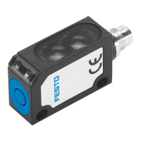
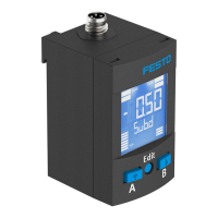
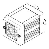
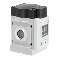
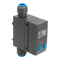
Provides a general overview of the air gap sensor and its components.
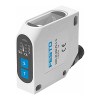
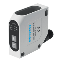
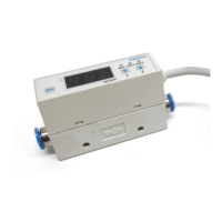
Details the various features and specifications of the air gap sensor variants.
Lists the default configuration settings for the air gap sensor.
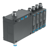
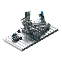
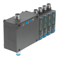
Explains the system design, consisting of control and sensor modules.
Describes the different operating modes and their functions.
Details the operational capabilities and function range of the sensor.
Explains how binary signals and switching signals are configured and used.
Describes the graphic display for distance monitoring in RUN mode.
Details parameter options for suppressing spurious pulses.
Explains how to switch the numerical display on or off.
Describes how to set and use a security code for protection.
Explains how to display and reset min/max values.
Provides instructions for the mechanical installation of sensor modules.
Details the pneumatic connections and arrangement for the system.
Explains the electrical connections and pin allocation for the control module.
Explains the symbols used on the device's display.
Describes the meaning of the bar graph segments on the display.
Illustrates symbols used to navigate and understand the menu structure.
Details the basic operating status after power-up.
Explains the INFO and SHOW modes for viewing data and settings.
Covers entering EDIT mode, setting binary signals, and special menus.
Describes the TEACH mode for setting switching points.
Provides instructions to reset the sensor module to its default factory settings.
Explains how to use a differential pressure regulator for faster response times.
Lists error codes, their meanings, and troubleshooting steps.
| Brand | Festo |
|---|---|
| Model | SOPA-C series |
| Category | Accessories |
| Language | English |