Do you have a question about the Festo SPAU and is the answer not in the manual?
Lists all available documents for the product, including links to the Festo website for further information.
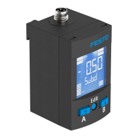
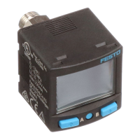
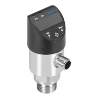
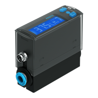
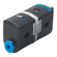
Specifies the pressure sensor SPAU is for monitoring compressed air and inert gases in piping.
Provides essential safety guidelines for product operation, maintenance, and environment.
Details the product's application scope and compliance with UL certification for USA and Canada.
Describes the different operating modes of the sensor, such as RUN, SHOW, EDIT, and TEACH modes.
Details the various switching functions available for monitoring pressure thresholds and ranges.
Provides instructions and precautions for the mechanical and pneumatic installation of the sensor.
Outlines electrical connection requirements and safety warnings for installation.
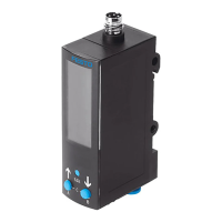
Explains the LCD display elements and their meanings during operation and configuration.
Details how to display and reset parameters for the switching output OutA.
Explains how to display parameters for switching output OutB or analogue output OutD.
Instructions on how to reset all parameters to their factory default settings.
Lists general fault descriptions, their causes, and recommended remedies.
Details specific fault codes and remedies for device variants equipped with an LCD display.
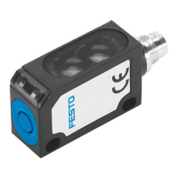
Lists fault indicators and remedies for device variants lacking an LCD display.
| Type | SPAU |
|---|---|
| Operating pressure | 0 ... 10 bar |
| Measuring range | 0 ... 10 bar |
| Switching output | PNP/NPN |
| Protection class | IP65 |
| Accuracy | ±1% of full scale |
| Repetition accuracy | <= ± 0.2 % FS |
| Analogue output | 0 ... 10 V, 4 ... 20 mA |
| Process connection | G1/4 |
| Medium | Compressed air |
| Port size | G1/4 |
| Material | Stainless steel |
| Electrical connection | M12 plug connector |