Do you have a question about the Festo SPAN-B Series and is the answer not in the manual?
Describes different operating modes of the sensor, including RUN, SHOW, EDIT, and TEACH.
Details the threshold value comparator and window comparator switching functions (N/O and N/C).
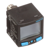
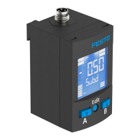
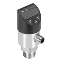
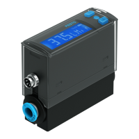
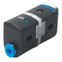
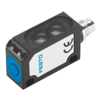
Illustrates and labels the physical components and connections of the sensor.
Provides instructions for mounting the sensor, considering environmental factors and pneumatic connections.
Details the wiring for the sensor's electrical connection, including pin assignments and colours.
Explains the different elements and indicators shown on the sensor's LCD display.
Describes the initial startup procedure and basic operating status of the sensor.
Outlines how to access and view the sensor's current measured values and settings.
Explains how to unlock parameter settings using a security code.
Guides users through setting the threshold value comparator and window comparator parameters.
Details the process for modifying various device settings via the SPEC menu.
Describes how to copy settings from a master sensor to a device sensor.
Provides instructions for calibrating the sensor's zero point.
Details the procedure for teaching the first and second switching points (TP1, TP2).
Explains how to reset the sensor to its original factory settings.
Provides a table listing possible malfunctions, their causes, and recommended remedies.
Lists general specifications, approvals, and operating medium details.
Details specifications related to the switching output, including current, voltage, and protection.
Covers displayable units, setting ranges for threshold values, and hysteresis.
Details housing materials, protection class, shock, and vibration resistance.
The Festo SPAN-B pressure sensor converts pneumatic pressure values (relative pressure) into electrical signals for control or regulation. It utilizes a piezoresistive sensor element with a downstream electronic evaluation unit, connecting to a higher-level system via a switching output. This output can be configured to monitor a threshold value or a pressure range, with optional PNP or NPN and normally open (N/O) or normally closed (N/C) settings.
The sensor operates in several modes:
The SPAN-B offers two primary switching functions:
Parameters such as filter time constant, unit for pressure indicator, zero point synchronization (zero adjust), economy mode period for display background lighting, and security code activation can be configured. The device also supports replication of parameters from a master sensor to a device sensor.
| Brand | Festo |
|---|---|
| Model | SPAN-B Series |
| Category | Accessories |
| Language | English |