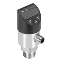
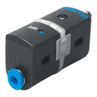
SPAN-B -...- G18FPM/M5FAL with mounting bracket
– Recommendation for the variant "SPAN-B-...-G18FPM..": use type OL-1/8
sealing ring at the pneumatic connection.
Fig. 3 Example with G18FPM
Front panel insert SAMH-PN-F
Fig. 4 Size of the front panel cut-out in mm
1
Panel frame
2
Clamping element
Fig. 5
1. Fasten panel frame to the sensor.
2. Guide sensor into the cut-out on the front panel from the front.
3. Attach the clamping element and press until the clamping element clicks into
place.
5.2 Electrical
WARNING!
Risk of injury due to electric shock.
• For the electric power supply, use only PELV circuits that ensure a reliable
electric disconnection from the mains network.
• Observe IEC60204-1/EN60204-1.
• Connect sensor.
– Take the maximum permissible line length into account: 30m.
Pin Colour
1)
Allocation Plug L1
1 Brown (BN) Operating voltage +24 V DC
2 Black (BK) Switching output OutA
3 White (WH) NC (not connected)
4 Blue (BU) 0V
1) Colours apply for connecting cables NEBS-L1… or electrical adapter SASC-P4… with NEBU-M8…
Tab. 4
Circuit diagram SPAN-B-PN
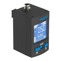
Fig. 6 SPAN-B-PN
6 Commissioning
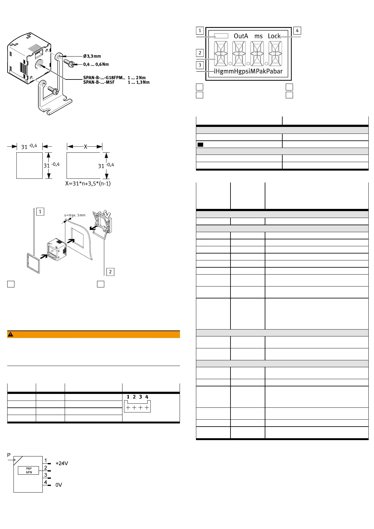
6.1 LCD display
1
Switching status indication
2
Main display (e.g.measurement
value)
3
Pressure units
4
Status information
Fig. 7 LCD display
Example for LCD display Meaning
Output display
[OutA] Switching output OutA selected
[OutA] Switching output OutA set
Status information/signal indicator
[Lock] Security code activated
[SPEC] Special menu selected
Tab. 5
Example for
LCD display
Main display
Example for
LCD display
Alternating
display
Meaning
Measured value indicator and unit in the RUN mode
[– 0.53] [bar] Measured value indicator (here: negative value) and unit
Menu for switching output OutA
_|¯ [Fctn] Threshold value comparator
_|¯|_ [Fctn] Window comparator
[1.80] [SP] Switching point value
[2.45] [SP.Lo] Value of lower switching point
[6.45] [SP.Hi] Value of upper switching point
[0.50] [HY] Hysteresis value
[NO] [LOGC] Switching behaviour:
[N/O] = normally open, [N/C] = normally closed
[PNP] [Out] Shift of the switching outputs (binary) between PNP and
NPN
[bLUE] [COLR] Display colour:
[bLUE] = blue, colour change function is deactivated
[R.ON] = red when switching output set
[R.OFF] = red when the switching output is not set
Note: independent of the settings [COLR], the red colour
change appears with some malfunctions.
Extreme values (only SHOW mode)
[1.64] [MIN] Minimum measured pressure since switch-on or the last
reset
[8.50] [MAX] Maximum measured pressure since switch-on or the last
reset
Menu for device settings (SPEC)
[16] [Filt]/[ms] Value of the filter time constant for the pressure measure-
ment signal
[bar] [Unit] Unit for the pressure indicator
[OFF] [Z.AdJ] [OFF] = zero point synchronisation (zero adjust) deactiv-
ated
[ON] = offset correction for measured value indicator and
switching points possible
[40] [Eco]/[s] Economy mode: period after which the display background
lighting is switched off
[OFF] [Code]/[Lock] Activation and determination of the security code
[OFF] [MASt] Activation of the IO-Link master function for replication of
parameters
Tab. 6
6.2 Switching on the sensor (RUN mode)
• Switch on the operating voltage.
Ä
Current measured value is displayed. The sensor is in the basic status
(RUN mode).
The basic status can be reached from other modes by:
– Press and hold Edit pushbutton for 3 seconds
– Expiration of a monitoring time (time-out)
6.3 Displaying parameters (SHOW mode)
Requirement: the sensor is ready for operation (RUN mode).

 Loading...