Pressure sensor SDE5
Festo AG & Co. KG
Ruiter Straße 82
73734 Esslingen
Germany
+49 711 347-0
www.festo.com
Operating instructions
Original instructions
8078140
2017-09e
[8068031]
For all available product documentation è www.festo.com/pk
1 Product description
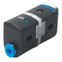
1.1 Overview
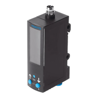
SDE5 installed on the MS series
service unit
3
2
1
4
1
2
3
5
1 Electrical connection
2 LED indicator (continuous
transmission of the LED indicator
through fibre-optic cable)
3 Edit button (not on SDE5-…X)
4 Connection 2 for compressed air
or vacuum
5 Connection 1 for compressed air
or vacuum
Fig. 1
1.2 Characteristics
Key feature Order code Specification
Type SDE5 Pressure sensor
Pressure
measuring
range
-V1/-B2/-D2/
-D6/-D10
è Chapter 10 Technical data.
Supply port Relative pressure
-Z Differential pressure
Output
function
1)
-FP Freely programmable
-O
-C
Normally open contact (NO), fixed hysteresis, mode 0
Normally closed contact (NC), fixed hysteresis, mode 0
-O1
-C1
Normally open contact (NO), fixed hysteresis, mode 1
Normally closed contact (NC), fixed hysteresis, mode 1
-O2
-C2
Normally open contact (NO), teachable hysteresis, mode 2
Normally closed contact (NC), teachable hysteresis, mode 2
-O3
-C3
Normally open contact (NO), fixed hysteresis, mode 3
Normally closed contact (NC), fixed hysteresis, mode 3
-NF Analogue output 0 … 10 V
Pneumatic
connection
-Q4/-Q6/
-T532/-T14
At both ends for standard O.D. tubing
-N-4 mm/-N-6 mm/-N-Â/-N-¼
-Q4E/-Q6E/
-T532E/-T14E
At one end for standard O.D. tubing
-N-4 mm/-N-6 mm/-N-Â/-N-¼
Electrical
output
-P/-N Switching output PNP/NPN
-V Pressure proportional voltage 0 ... 10 V
Electrical
connection
-K Cable, 2.5 metres long, 3-core
-M8 Plug connector M8x1, 3-pin
Teach point -X
-Y
X teach point permanently set
Y teach point permanently set
1) Signal curves, switching functions and operating modes èFig. 14 and Fig. 15
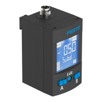
Fig. 2
2 Function and application
The pressure sensor SDE5 is intended for the proper monitoring of the pressure
inthe compressed air system. The SDE5 converts pneumatic pressure values into
apressure proportional voltage. Depending on the design of the pressure sensor,
this signal is converted into a digital switching signal (SDE5-…-P-…/SDE5-…-N-…)
or it is amplified for an analogue output (SDE5-…-NF-…-V).
The monitored pressure values record either the relative pressure or the
differential pressure (SDE5-…-Z-…).
The pressure sensor with switching output closes or opens a circuit when the
switching pressure is reached. The switching element function is preset at the
plant and can only be modified with the SDE5-…-FP-…. The SDE5 is available with
different switch/teach functions (è Fig. 2).
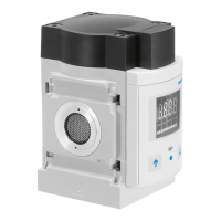
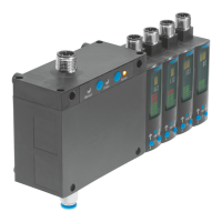
MS series service unit with pressure sensor SDE5
The pressure sensor SDE5 on the series MS service unit is already permanently
attached and pneumatically connected on delivery. Fig. 3 shows the allocation
between the MS service unit and the attached pressure sensor.
MS series service unit Attached pressure sensor
MS4/6-…-AD7 SDE5-D10-O-…-P-M8
MS4/6-…-AD8 SDE5-D10-C-…-P-M8
MS4/6-…-AD9 SDE5-D10-O3-…-P-M8
MS4/6-…-AD10 SDE5-D10-C3-…-P-M8
Fig. 3
3 Requirements for product use
Use the product in its original status, without any unauthorised product
modifications.
Observe the specified limits (e.g. operating medium, pressures, forces,
temperatures).
Take into consideration the ambient conditions at the location of use.
Observe the regulations which apply in your location (e.g. from trade
associations or from national institutions).
Remove everything used for protection during transport such as protective wax,
films, caps and cardboard boxes. The material used in the packaging has been
specifically chosen for its recyclability (exception: oil-impregnated paper =
residual waste).
The device is intended for use in an industrial environment. Measures may need
to be implemented in residential areas for interference suppression.
Remove dirt particles in the supply lines by blowing out the pipes and hoses.
This protects the device from premature failure or heavy wear.
Range of applications and certifications
The information in this section, in combination with the UL marking on the product,
must be observed in order for there to be compliance with the certification
conditions of Underwriters Laboratories Inc. (UL) for USA and Canada. Observe the
following English-language remarks from UL:
This device is intended to be used with a Class 2 power source or Class 2
transformer in accordance with UL1310 or UL1585.
As an alternative a LV/C (Limited Voltage/Current) power source with one of the
following properties can be used:
– This device shall be used with a suitable isolating source such that the
maximum open circuit voltage potential available to the product is not more
than 30 V DC and the current is limited to a value not exceeding 8 amperes
measured after 1 minute of operation.
– This device shall be used with a suitable isolating source in conjunction with
afuse in accordance with UL248. The fuse shall be rated max. 3.3 A and be
installed in the 30 V DC power supply to the device in order to limit the available
current.
Note that, when more than one power supply or isolating device is used,
connection in parallel is not permitted.
In determining the acceptability of the combination, the following details are to be
examined:
– The suitability of the final mounting is to be determined.
– The devices are to be mounted in an enclosure with adequate strength and
thickness.
– The devices have not been examined for field wiring. The suitability of the final
application is to be determined.
UL approval information
Product category code NRNT2 (USA) or
NRNT8 (Canada)
File number E253738
Considered standards UL 508, 17th edition,
C22.2 No. 14-95
UL mark
Fig. 4