Pressure sensor SDE1-…
Festo AG & Co. KG
Postfach
73726 Esslingen
Germany
+49 711 347-0
www.festo.com
Operating instructions 8048045
1511h
[8048047]
Original: de
Pressure sensor SDE1 English..........................................
1 Product description
The operating instructions describe the entire function range. The function range is
limited, depending on the product variant.
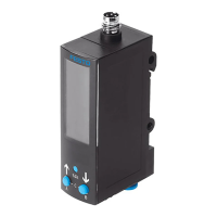
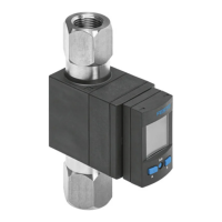
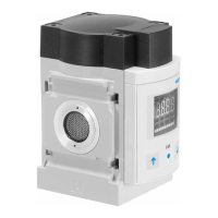
1.1 Structure
1
2
3
4
5
6
1 Pneumatic connection
(design type-dependent)
2 Electrical connection
(design type-dependent)
3 B key
4 Edit button
5 A key
6 Display
Fig. 1
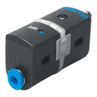
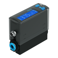
1.2 Characteristics
Characteristic Value Description
Type SDE1 Pressure sensor
Pressure measuring
range
-V1, -B2, -D2,
-D6, -D10
è 11 Technical data
Accuracy -G2 Accuracy 2 %
Pneumatic connection
and mounting
-R18
1)
Male thread Rx
-R14
1)
Male thread R¼
-MS4 For adapting to MS4-series service units
-MS6 For adapting to MS6-series service units
-H18 Relative pressure, female thread Gx, H-rail mounting
-W18 Relative pressure, female thread Gx, wall or surface
mounting
-FQ4 Push-in connector QS-4, front panel mounting
-HQ4 Push-in connector QS-4, H-rail mounting
-WQ4 Push-in connector QS-4, wall or surface mounting
Display -C LCD display with backlighting
-L Illuminated LCD display
Characteristic Code Type designation
Electrical output -P1 1 switching output PNP
-P2 2 switching outputs PNP
-PU 1 switching output PNP and 0…10 V analogue
-PI 1 switching output PNP and 4…20 mA analogue
-2I 2 switching outputs PNP and 4…20 mA analogue
-N1 1 switching output NPN
-N2 2 switching outputs NPN
-NU 1 switching output NPN and 0…10 V analogue
-NI 1 switching output NPN and 4…20 mA analogue
Electrical connection -M8 M8 plug connector
-M12 M12 plug connector
Electrical accessories -G Straight socket, cable 2.5 m
-G5 Straight socket, 5 m cable
-w Angled plug socket, 2.5 m
-W5 Angled plug socket, 5 m cable
1) For example, for mounting on an MS- or D-series service unit
Fig. 2
2 Security
Intended use
The pressure sensor SDE1 is intended for monitoring pressure in piping or terminals.
General safety information
– The product may only be used in its original status without unauthorised modi
fications.
– Only use the product if it is in an excellent technical status.
– The product is intended for use in industrial environments. Measures may need
to be implemented in residential areas for radio interference suppression.
– Take into consideration the operating conditions at the location of use.
– Observe the specifications on the rating plate.
– Comply with all applicable national and international regulations.
Disposal
– Observe the local specifications for environmentally friendly disposal.
Range of applications and certifications
In combination with the UL mark on the product, the information included in this
section is also applicable for compliance with the certification requirements of
Underwriters Laboratories Inc. (UL) for USA and Canada. Observe the following
English-language remarks from UL:
UL approval information
Product category code NRNT2 (USA)
NRNT8 (Canada)
File number E253738
Considered standards UL 508, 17th edition, C22.2 No. 14-95
UL mark
Fig. 3
Only for connection to an NEC/CEC Class 2 supply.
Raccorder uniquement a un circuit NEC/CEC Classe 2.
Technical data
Max. surrounding air temperature 50 °C / 122 °F
Fig. 4
This device is intended to be used with a Class 2 power source or Class 2 trans
former in accordance with UL1310 or UL1585.
As an alternative, an LV/C (Limited Voltage/Current) power source with one of the
following properties can be used:
– This device shall be used with a suitable isolating source such that the maxim
um open circuit voltage potential available to the product is not more than
30 V DC and the current is limited to a value not exceeding 8 amperes measured
after 1 minute of operation.
– This device shall be used with a suitable isolating source in conjunction with a
fuse in accordance with UL248. The fuse shall be rated max. 3.3 A and be in
stalled in the 30 V DC power supply to the device in order to limit the available
current.
Note that, when more than one power supply or isolating device is used, connec
tion in parallel is not permitted.