Do you have a question about the Festo Span Series and is the answer not in the manual?
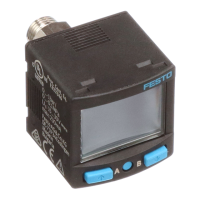
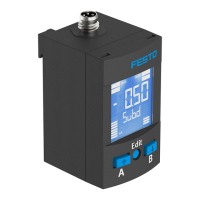
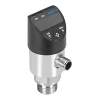
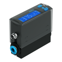
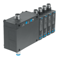
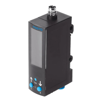
Provides a visual overview of the pressure sensor SPAN and its components.
Details the technical characteristics and specifications of the pressure sensor variants.
Specifies the intended application of the pressure sensor for monitoring compressed air and inert gases.
Outlines crucial safety guidelines for the proper and safe operation of the product.
Advises on the environmentally friendly disposal of the product.
Describes the different operating statuses of the sensor, such as RUN, SHOW, and EDIT modes.
Explains the different switching functions like threshold value and window comparators.
Details the auto difference monitoring function for pressure constancy.
Covers mechanical mounting considerations and pneumatic connections for the sensor.
Provides essential information and warnings regarding the electrical connection of the sensor.
Explains the components and information displayed on the sensor's LCD screen.
Describes the initial steps to switch on the sensor and enter the RUN mode.
Details how to view sensor parameters using the SHOW mode and A/B keys.
Guides on how to enter the security code to unlock parameter settings.
Explains the process for configuring the switching outputs for OutA and OutB.
Outlines how to modify device settings like filter and unit via the EDIT mode.
Describes the procedure for setting the parameters of the analogue output.
Details how to copy parameters from a master sensor to a device sensor.
Presents a visual overview of the sensor's menu structure and navigation.
Explains how to perform zero point synchronization for accurate pressure readings.
Describes the process of teaching switching points for output configuration.
Warns about potential property damage due to high temperatures during operation.
Provides instructions on how to reset the sensor's parameters to factory default settings.
Outlines the basic steps for maintaining and caring for the sensor.
Details the procedure for safely disconnecting and removing the sensor.
Lists common malfunctions and provides corresponding troubleshooting steps and remedies.
Directs users to the Festo website for a catalogue of compatible accessories.
Lists general specifications like approval certificates, materials, and operating medium.
Provides specific pressure measuring ranges for different sensor variants.
Details the IO-Link protocol version, profiles, and communication parameters.
| Material seals | NBR |
|---|---|
| Mounting type | Inline |
| Operating medium | Compressed air |
| Ambient temperature | -20 ... 60 °C |
| Medium temperature | -20 ... 60 °C |