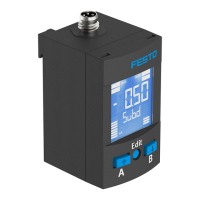
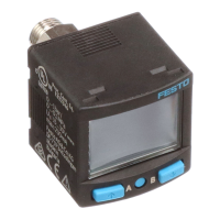
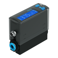
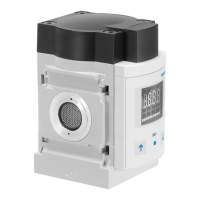
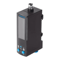
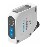
The Festo SPAE pressure sensor is a device designed for recording relative pressure in pneumatic applications. It converts pneumatic pressure values into a voltage proportional to the pressure, utilizing a piezoresistive sensor element for measurement. This sensor can be connected to a higher-level system via a switching output or an IO-Link interface, offering flexibility in integration.
Function Description
The SPAE pressure sensor operates by continuously monitoring pressure and providing a switching output based on configured threshold values or pressure ranges. It supports both PNP and NPN switching outputs, as well as normally open (N/O) or normally closed (N/C) output configurations. Through the IO-Link interface, process values can be read out, and parameters can be changed and transmitted to additional devices.
The sensor has several operating statuses:
- RUN mode: The basic state after applying operating voltage, displaying the current measured value and selected switching status.
- SHOW mode: Displays the current settings.
- EDIT mode: Allows for setting or modification of parameters.
- TEACH mode: Accepts the current measured value to determine the switching point.
The sensor offers various switching functions:
- F0 (Threshold value comparator): Uses one switching point (P1).
- F1 (Threshold value comparator): Uses one switching point (P1), calculated as half the sum of two teach-in points (tP1 + tP2)/2.
- F2 (Threshold value comparator): Uses two switching points (P1, P2), where tP1 = P1 and tP2 = P2.
- F3 (Window comparator): Uses two switching points (P1, P2), where tP1 = P1 and tP2 = P2.
Hysteresis is adjustable from 0 to 99, corresponding to 0 to 9.9% FS (Full Scale).
Important Technical Specifications
- Operating Medium: Compressed air in accordance with ISO 8573-1:2010 [7:4:4], suitable for lubricated operation.
- Temperature Range:
- Medium: 0 to 50 °C
- Ambient: 0 to 50 °C
- Storage: -20 to +80 °C
- Accuracy:
- At room temperature: ±1.5 % FS
- In ambient temperature range: ±2.5 % FS
- Repetition accuracy: ±0.3 % FS
- Temperature Coefficient: Typ. ±0.05 % FS/K
- Switching Output:
- Switch-on/off time: Typ. 1 ms (with filter time constant = Off, default)
- Max. output current: 100 mA
- Capacitive load maximum DC: 100 nF
- Voltage drop: Max. 1.2 V
- Inductive protective circuit: Present
- Short circuit current rating: Yes
- Overload protection: Present
- Electrical Data:
- Operating voltage range DC: 18 to 30 V
- No-load supply current: < 11 mA
- Ready-state delay: < 30 ms
- Reverse polarity protection: All connections against one another
- Electrical connection: Cable 3-wire, open end
- Max. permissible line length: 30 m (with IO-Link 20)
- Cable sheath material: PVC
- Mechanical Data:
- Housing material: Reinforced PA
- Key material: POM
- Mounting position: Any, but condensation accumulation in the sensor should be avoided.
- Environmental Data:
- Degree of protection: IP 40 (in accordance with EN 60529)
- Protection class: III (in accordance with DIN VDE 0106-1)
- Shock resistance: 30 g acceleration with 11 ms duration (half-sine) (in accordance with EN 60068-2)
- Vibration resistance: 10 to 60 Hz: 0.35 mm / 60 to 150 Hz: 5 g (in accordance with EN 60068-2)
- Pollution degree: 3
- IO-Link Specifications:
- IO-Link protocol: V1.1
- IO-Link profile: Smart Sensor Profile (Function classes: 0x8000, 0x8001, 0x8002, 0x8003, 0x8004)
- Communication mode: COM2 (38.4 kbaud)
- Port type: A
- Process data length IN: 2 bytes
- Process data content IN: Pressure monitoring BDC1/BDC2 (BinaryDataChannel), Pressure measurement value PDV 14 bit (Process-DataVariable)
- Pressure Gauge Ranges (example variants):
- -B2: -0.1 to 0.1 MPa (-1 to 1 bar, -14.5 to 14.5 psi)
- -B11: -0.1 to 1 MPa (-1 to 10 bar, -14.5 to 145 psi)
- -V025: 0 to -0.025 MPa (0 to -0.25 bar, 0 to -3.625 psi)
- -V05: 0 to -0.05 MPa (0 to -0.5 bar, 0 to -7.25 psi)
- -V1: 0 to -0.1 MPa (0 to -1 bar, 0 to -14.5 psi)
- -P025: 0 to 0.025 MPa (0 to 0.25 bar, 0 to 3.625 psi)
- -P05: 0 to 0.05 MPa (0 to 0.5 bar, 0 to 7.25 psi)
- -P1: 0 to 0.1 MPa (0 to 1 bar, 0 to 14.5 psi)
- -P2: 0 to 0.2 MPa (0 to 2 bar, 0 to 29 psi)
- -P6: 0 to 0.6 MPa (0 to 6 bar, 0 to 87 psi)
- -P10: 0 to 1 MPa (0 to 10 bar, 0 to 145 psi)
- Overload Ranges (example variants):
- -B2: -0.1 to 0.5 MPa (-1 to 5 bar, -14.5 to 72.5 psi)
- -B11: -0.1 to 1.5 MPa (-1 to 15 bar, -14.5 to 217.5 psi)
- -V025: -0.1 to 0.1 MPa (-1 to 1 bar, -14.5 to 14.5 psi)
- -V05: -0.1 to 0.2 MPa (-1 to 2 bar, -14.5 to 29 psi)
- -V1: -0.1 to 0.5 MPa (-1 to 5 bar, -14.5 to 72.5 psi)
- -P025: -0.1 to 0.1 MPa (-1 to 1 bar, -14.5 to 14.5 psi)
- -P05: -0.1 to 0.2 MPa (-1 to 2 bar, -14.5 to 29 psi)
- -P1: -0.1 to 0.5 MPa (-1 to 5 bar, -14.5 to 72.5 psi)
- -P2: -0.1 to 0.6 MPa (-1 to 6 bar, -14.5 to 87 psi)
- -P6: -0.1 to 1.5 MPa (-1 to 15 bar, -14.5 to 217.5 psi)
- -P10: -0.1 to 1.5 MPa (-1 to 15 bar, -14.5 to 217.5 psi)
- UL/CSA Certification:
- Product category code: QUYX2 (USA) or QUXY8 (Canada)
- File number: E322346
- Considered standards: UL 61010-1, CAN/CSA 22.2 No. 61010-1
- Pollution degree: 2
- Operating temperature: 0 to 50 °C / 32 to 122 °F
- Relative humidity: 0 to 100%
- For use in wet locations: No
Usage Features
- Assembly: The sensor can be mounted in several ways depending on the product variant:
- On mounting clip (SPAE-...-Q...): Slides into a SAMH mounting clip with the cable outlet at the top or bottom. Unused pneumatic ports should be closed with a blanking plug.
- On plate (SPAE-...-F): Secured with M2 screws (max. 0.3 Nm) to a flange hole pattern, ensuring the sealing ring is correctly seated. The pressure port hole has a maximum diameter of 2 mm.
- On QS plug connector (SPAE-...-S...): Inserted into the QS plug connector until it stops.
- Commissioning:
- Displaying parameters (SHOW mode): Briefly pressing the operating key cycles through displayed parameters.
- Setting sensor (EDIT mode): Pressing and holding the operating key enters EDIT mode. Parameters can be adjusted in two stages: rough adjustment (steps of ten) and precision adjustment (steps of one).
- Teaching switching point (TEACH mode): Allows setting switching points by applying a teach pressure. For F0, one teach pressure sets P1. For F1, F2, and F3, two teach pressures (tP1, tP2) define the switching points.
- Security code: Parameter entry can be blocked by an enabled security code, requiring input to unblock.
- Operating key: Used to select switching functions and set parameters. It is time and context-dependent; if not actuated for approx. 12 seconds, the sensor automatically switches to RUN mode, saving changes (except in TEACH mode and min./max. display).
- Replicating parameters: A master sensor can replicate its parameters to a device sensor via the IO-Link master function. Requirements include both sensors having the same design (device ID), the device sensor's switching output configured to PNP and unswitched, and parameterization not blocked via IO-Link.
- Display components: LEDs indicate operating status (IO-Link communication active, switching output switched/not switched, SHOW mode, EDIT mode, TEACH mode). The display shows current measured values, functions, and parameter values.
- Display options: Numeric indicator alignment can be set to default ('do') or rotated 180° ('op'). The display can be set to always on ('On') or switch off after 1 to 20 minutes ('1'...'20').
Maintenance Features
- Fault clearance: The manual provides a table of common malfunctions, their causes, and remedies. Examples include:
- No display: Caused by no operating voltage, unreliable voltage, or swapped electrical connections. Remedy: Apply correct voltage, connect according to circuit diagram, or replace device.
- No measured value indicator in RUN mode: Caused by display switch-off activated. Remedy: Press operating key, set 'On' value.
- Display flashes in RUN mode: Measuring range exceeded. Remedy: Hold measuring range.
- Implausible measured value: Wrong display orientation. Remedy: Check display orientation.
- Indicator or switching output does not respond: Short circuit/overload at output or incorrect switching point. Remedy: Eliminate short circuit/overload, repeat teach-in.
- 'Er'/'LC' (Incorrect security code): Remedy: Enter security code.
- 'Er'/'Co' (IO-Link communication error): Remedy: Check device sensor setting (Pn), check line.
- 'Er'/'Id' (Device ID error): Remedy: Use sensors with the same pressure range (device ID) when replicating.
- 'Er'/'bY' (Switching output is active): Remedy: Check device settings.
- 'Er'/'01' (Device error): Remedy: Replace device.
- 'Er'/'17' (Undervoltage): Remedy: Apply permissible operating voltage.
- 'Er'/'20' (Temperature fault): Remedy: Check operating conditions, replace device.
- 'Er'/'21' (Short circuit): Remedy: Eliminate short circuit.
- Restoring factory settings (Restore): This function deletes current settings. It is performed by switching off the operating voltage, pressing and holding the operating key, then switching on the operating voltage until 'rS' appears, and finally releasing the key.
- Removal: To remove the sensor, switch off operating voltage and compressed air, disconnect electrical and pneumatic connections, then release fasteners (or latch for mounting clips) and remove the sensor.