6 Installation
6.1
Installation, electrical
WARNING
Risk of injury due to electric shock.
• For the electric power supply, use only PELV circuits that ensure a reliable electric disconnection
from the mains network.
• Observe IEC60204-1/EN60204-1.
• Connect the sensor.
–
Note maximum permissible cable lengths
è
11 Technical data.
– Only route the signal line and power supply in a common line.
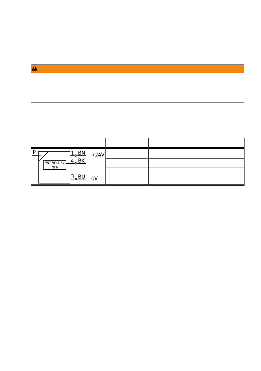
Circuit diagram and wire assignment
Circuit diagram Core colour Allocation
Brown (BN) Operating voltage +24 V DC
Black (BK) Switching output or IO-Link (C/Q line)
Blue (BU) 0V
Tab. 7: Circuit diagram
7
Commissioning
7.1
Displaying parameters in SHOW mode
Requirement: the sensor is ready for operation and is in RUN mode.
1. Press the operating key briefly.
Ä
The sensor is in SHOW mode. The first parameter set is displayed.
2. Press the operating key to display each of the following parameters.
Ä
The other parameters are displayed.
7.2 Setting sensor in EDIT mode
Requirement: the sensor is ready for operation and is in RUN mode.
Entering security code
If the security code is enabled, the parameter entry option is blocked: ‘LC’ flashes briefly, then the
value 1 appears.
1. Press the operating key repeatedly until the security code is set.
2. Press and hold the operating key.
Ä
The parameter entry option is unblocked.