Flow Sensor SFAB
Festo AG & Co. KG
Postfach
D−73726 Esslingen
++49/711/347−0
www.festo.com
Operating instructions 743 851
0811NH
Original: de
Note
Installation and commissioning may only be performed in accordance with thess
instructions by technicians with appropriate qualifications.
Note
The product is suitable for use only for industrial purposes.
In residential areas, measures for radio interference suppression may be
necessary. It is not suitable for commercial invoicing, such as for measurement
of air consumption in public utilities.
1 Product description
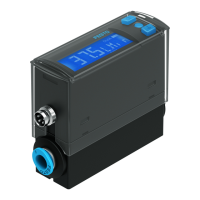
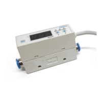
1.1 Overview
9
2
3
4
1
5
6
7
8
1 Supply por t 1
èMarking on the product
2 Display
3 B button
4 Edit button
5 A button
6 Plug for electrical
connection(M12)
7 Supply por t 2
èMarking on the product
8 Hole for fitting the plate
9 Fastening slide for hat rail fitting
and wall fitting (rear)
Fig.1
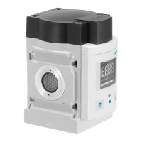
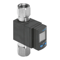
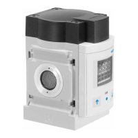
1.2 Characteristics
Feature Order code Design
Basic version SFAB Flow sensor
Flow measuring range
−10 Max. 10l/min
−2SV 2x PNP or NPN, 1 analogue output 0 Ū 10 V
Electrical connection −M12 Plug M12x1, 5−pin, A−coded
Additional function at −D Final control element
Electrical accessories
1)
−2.5S Connecting cable, straight socket, cable 2.5m
−5S Connecting cable, straight socket, cable 5m
−2.5A Connecting cable, angled socket, cable 2.5m
−5A Connecting cable, angled socket, cable 5m
1) Included in the scope of delivery.
Fig.2
2 Function and application
The SFAB is designed to monitor changes in flow and air consumption for suitable
media in piping systems or end devices in industry; suitable media è chapter 11
Technical specifications. Measurement is carried out by means of a thermal
procedure. The amount of heat, which is drawn from a heated surface of the
sensor by the medium flowing through it, is calculated here. Through the amount
of heat removed, the flow or accumulated air consumption is determined and
shown on the display. The connection to higher−level systems is made via 2 binary
outputs (Out A/B) and one analogue output (Out C). Switching points can be set
for both binary outputs. For flow measurement, switching points are possible for
both binary outputs, and for accumulated air consumption meaurement a
consumption switch impulse for outputA (Out A). The combination of accumulated
air consumption measurement (Out A) and flow measurement (Out B) is possible.
The flow value is output via the analogue output. Up to a flow range of 200 l/min,
an integrated flow actuator can be optionally ordered. This permits setting the flow
with the precision described in chapter11, Technical specifications.
3 Conditions for the safe use of the product
Warning
Depending on the functioning of the machine/system, manipulation of signal
states may cause serious personal injury.
· Note that if the switching status of the outputs is modified in Edit mode,
the new status will be effective immediately.
· Activate the password protection (security code) in order to prevent the
unintentional change by unauthorised third parties è chapter5.4, section
Security code.
Warning
Use of the product in combination with prohibited media can result in personal
injury.
·Do not use the product in conjunction with inflammable gases, corrosive
gases, oxygen etc. The product is intended only for measuring the flow of
media, which are listed as suitable in the chapter11 Technical specifications.
Important
Condensation water, oil mist, foreign matter and other dir t in the compressed air
can damage the product and cause incorrect measurements and functional
disorders.
· Make sure that the specified air quality class is maintained for the operating
medium èchapter11 Technical specifications.