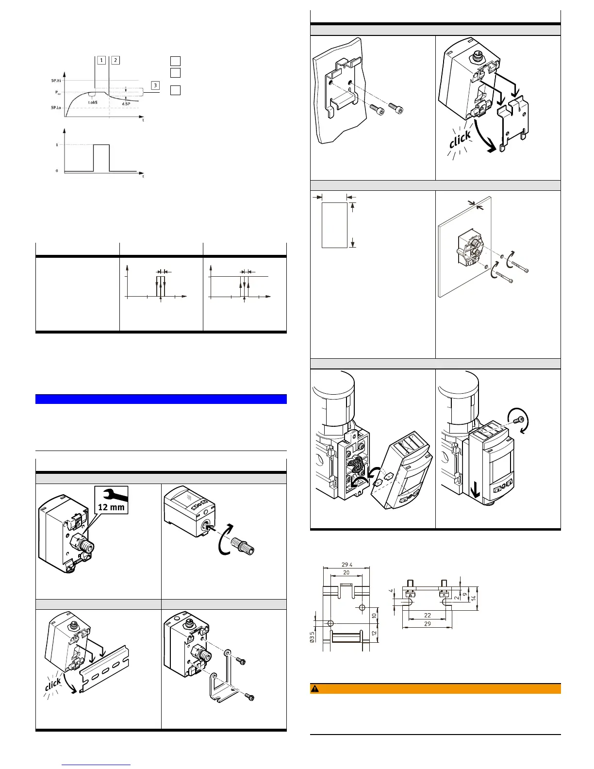
the output. The signal change signals the start of pressure monitoring. If the pres-
sure remains in the monitoring range [d.SP] around P
Ref
, the pressure is stable.
When the monitoring range is left (e.g. caused by a leakage in the system), the
output switches back.
1
Reference value is determined
2
Measured value deviates by
[d.SP] from the reference value
3
Monitoring range
Fig. 2
The parameters [SP.Lo], [SP.Hi], [t.obS] and [d.SP] can be configured by the user.
The greater [t.obS] is set, the more constant the pressure signal must be to estab-
lish the reference value P
Ref
.
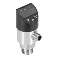
Function NO (normally open) NC (normally closed)
Switching function:
– 2 switching points (SP.Lo,
SP.Hi) for setting the valid
work range
– 1 switching point (d.SP)
for determination of the
monitoring area
TEACH mode
1)
:
– 2 Teach points (TP1, TP2)
– TP1 = SP.Lo, TP2 = SP.Hi
SP.Lo P
Ref
SP.Hi
d.SP
1
0
Out
p
1
SP.Lo P
Ref
SP.Hi
d.SP
0
Out
p
1) SP.Lo = smaller pressure value, SP.Hi = larger pressure value, independent of the Teach sequence
Tab. 5
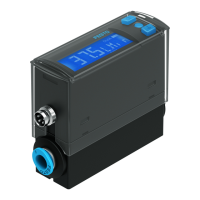
7 Installation
Work on the product should only be conducted by qualified personnel.
7.1 Mechanical and pneumatic
NOTICE!
An unfavourable mounting position can impair the function of the product.
• Mount the sensor so that no condensation from the compressed air lines can
gather in the device.
• Install the sensor so that it cannot be heated above the maximum permissible
operating temperature (plan for convection possibilities).
Installation
SPAU-...-T
– Seal connecting thread.
Tightening torque: max. 10Nm
(tightening torque M5 female thread: max. 2 Nm)
Tightening torque: max. 7Nm
SPAU-...-H SPAU-...-A
Screws: M3
Tightening torque: max. 0.5Nm
Mounting bracket hole pattern è Fig.3
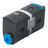
Installation
SPAU-...-W
1.
Wall mounting hole pattern è Fig.3
2.
SPAU-...-F
Front panel cut-out in mm – Guide sensor from the front into the cut-out
on the front panel.
– Attach the clamping plate and press until
the fastening slide clips in.
Screws: M3
Tightening torque: max. 0.7Nm
s < 2 mm: remove 1 washer
s < 1 mm: remove 2 washers
SPAU-...-MS...
1. 2.
Tightening torque: max. 1Nm
Tab. 6
7.1.1 Hole patterns
Fig. 3 Left wall mounting, right mounting bracket
7.2 Electrical
WARNING!
Risk of injury due to electric shock.
• For the electric power supply, use only PELV circuits that ensure a reliable
electric disconnection from the mains network.
• Observe IEC60204-1/EN60204-1.