Long signal lines reduce the resistance to interference.
• Adhere to the maximum permissible cable length of 30 m (20 m for IO-Link).
Maximum tightening torque of plug connector: M8 = 0.3Nm, M12 = 0.5Nm
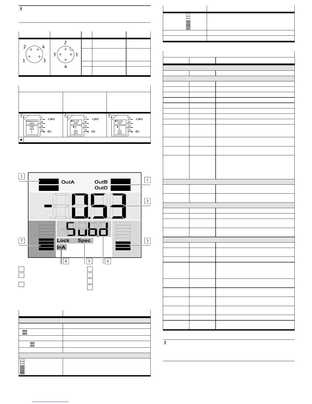
Connection -M8 Connection -M12 Pin Function Core colour
1 Operating voltage
+24 V DC
Brown (BN)
2 Switching output OutB
or analogue output
OutD
White (WH)
3 0 V DC Blue (BU)
4 Switching output OutA
IO-Link (C/Q line)
Black (BK)
Tab. 7
Circuit diagrams
SPAU-...-L-... with display SPAU-...-LK-V-.../SPAU-…-
LK-B-… without display,
analogue voltage output
on pin 2
SPAU-…-LK-A-… without
display, analogue current
output on pin 2
Usable output according to factory setting
Tab. 8
8 Commissioning
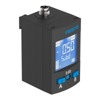
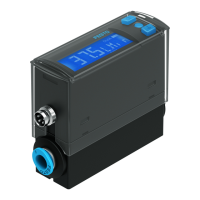
8.1 LCD display
1
Output display
2
Main display (e. g. measurement
value)
3
Bar graph for analogue output
(only visible for scaled analogue
output)
4
Lower display (e.g. unit)
5
Status information
6
Input display
7
Bar graph for input signal
Fig. 4
Example for LCD display Meaning
Output display
[OutA] Switching output OutA selected
Input signal InA: graphic display of the current measured value
related to the maximum measured value of the measuring range
Example for LCD display Meaning
Analogue output OutD with activated scaling
[Lock] Security code activated
[Spec] Special menu activated
Tab. 9
Example for LCD display
Main display Lower display Meaning
Measured value indicator and unit in the RUN mode
[– 0.53] [bar] Measured value indicator (here: negative value) and unit
Menu for the switching outputs (OutA and OutB)
[Edit] [bin] Edit menu for the switching outputs (binary)
_|¯ [Fctn] Threshold value comparator
d_|¯|_ [Fctn] Auto difference monitoring
_|¯|_ [Fctn] Window comparator
[1.80] [SP] Switchpoint value
[2.45] [SP.Lo] Value of lower switching point
[6.45] [SP.Hi] Value of upper switching point
[0.50] [HY] Hysteresis value
[18] [t.obS] / [MSEC] Time interval for determination of a mean value, which is
used to determine the pressure change and establish the
reference value.
[0.25] [d.SP] Threshold value of the differential pressure with auto dif-
ference monitoring
[NO] [logic] Switching characteristics: [NO] = normally open contact,
[NC] = normally closed contact
[bLUE] [COLR] Display colour:
[bLUE] = blue, colour change function is deactivated
[R.ON] = red when switching output set
[R.OFF] = red when the switching output is not set
Note: Independent of the settings [COLR], the red colour
change appears with some malfunctions.
Extreme values (only SHOW mode)
[1.64] [MIN] Minimum measured pressure since switch-on or the last
reset
[8.50] [MAX] Maximum measured pressure since switch-on or the last
reset
Menu for the analogue output (OutD)
[Edit] [ANLG] Edit menu for the analogue output
[1 _ 5] [Out] / [V] Output function of the analogue output
[93] [In.Hi] / [%] Scaling of the analogue output in percent of the final value
of the pressure measuring range
[3] [In.Lo] / [%] Scaling of the analogue output in percent of the initial
value of the pressure measuring range
Menu for device settings (Spec)
[Edit] [MENU] Edit menu for additional settings
[16] [Filt] / [MSEC] Value of the filter time constant for the pressure measure-
ment signal
[bar] [Unit] Unit for the pressure indicator
[OFF] [Z.AdJ] [OFF] = zero point synchronisation (zero adjust) deactiv-
ated
[ON] = offset correction for measured value indicator,
switching points and analogue output possible
[Unit] [Sub.d] Settings of the lower display in RUN mode: selected unit or
switching point of OutA or bar graph
[40] [Eco] / [SEC] Economy mode: period after which the display background
lighting is switched off
[PNP] [bin] / [Out] Shift of the switching outputs (binary) between PNP and
NPN
[bin] [Pin2] / [Out] Shift between switching output (binary) and analogue out-
put (lnA) at Pin 2
[OFF] [Code] Activation and determination of the security code (lock)
[OFF] [MASt] Activation of the IO-Link master function for replication of
parameters
Tab. 10
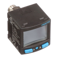
For device variants without LCD display:
• LED illuminated green: normal operation
• LED illuminated or flashes red: malfunction
8.2 Switch on sensor (RUN mode)
• Switch on the operating voltage.
Ä
Current measured value is displayed. The sensor is in the basic status
(RUN mode).
The basic status can be reached from other modes by:
– Pressing Edit button for 3 seconds
– Expiration of a monitoring time (timeout)
 Loading...