8.2 Electrical Installation
WARNING!
Risk of injury due to electric shock.
• For the electric power supply, use SELV or PELV circuits that guarantee a reliable electric discon-
nection from the mains network.
• Observe IEC60204-1/EN60204-1.
1. If a screened cable is used: earth the shield at the cable end farther away from the valve.
2. Install electrical connecting cable without squeezing, kinking or stretching.
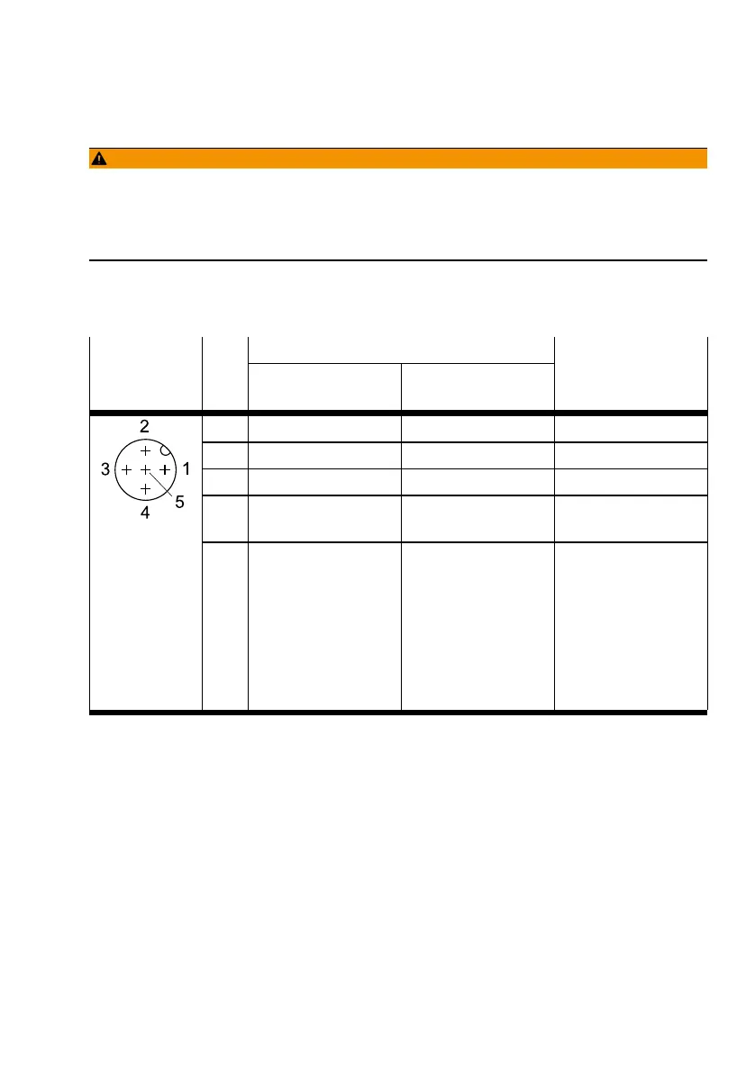
3. Tighten the electrical connecting cable onto plug M12. Tightening torque: maximum 0.3Nm
AllocationConnection Pin
Analogue Alternative (digital
input)
Wire colour
1)
(NEBU-M12...)
1 + 24 VDC + 24 VDC BN
2 Setpoint value (-) DI1 WH
3 GND GND BU
4 Setpoint value
(+)/PWM
DI0 BK
5 Actual value output
– related to pin 2
"Setpoint value (-
)" for type
VPPI -...- V1 -...
– related to pin 3
"GND" for
VPPI -...- A4 -...
DI2 GY
1) Colour code in accordance with IEC 60757:1983-01
Tab. 3 Pin Allocation for Plug M12, 5-pin
9 Commissioning
Requirements:
– The valve must be assembled.
– The pneumatic and electrical installation must be complete and checked.
1. Check operating conditions and critical limits è 14 Technical Data.
2. Switch on the power supply.
3. Switch on the compressed air supply.
4. Parameterise valve.
9.1 Parameterisation
The valve can be parameterised in the display menu using the 3 operating buttons.
Commissioning
11Festo — VPPI-...-D — 2019-12
 Loading...