11
is the distance between the bottom of the fence face
and the centerline of the mortising bit.
There are two features available for setting the
fence height:
a) with selection slide
X
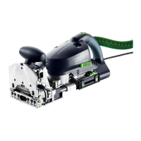
Loosen the clamp lever for the routing height
adjustment
[4-1]
.
X
Using the front handle
[4-2]
raise the front part
of the guide frame.
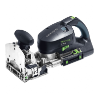
X
Use the selection switch to set
[4-4]
the desired
routing height
h
(10mm; 15mm; 20mm;
25 mm; 30 mm; 40 mm).
X
Press the front section of the guide frame down-
wards as far as the stop.
X
Close the clamp lever
[4-1]
.
b) freely selectable
X
Loosen the clamp lever for the routing height
adjustment
[4-1]
.
X
Using the front handle
[4-2]
raise the front sec-
tion of the guide frame.
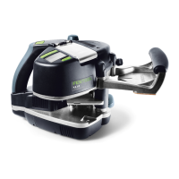
X
Pull the selection slide
[4-4]
as far as the stop
in the direction of the motor unit.
X
Set the desired routing height
h
using the scale
[4-3]
by moving the front section of the guide
frame vertically.
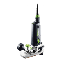
X
Close the clamp lever
[4-1]
.
L
The alignment of the clamp lever
[4-1]
can be
aligned by raising the levers. When tightened,
the levers should not protrude beyond the con-
tact surface.
Setting the Mortise Width
15 mm
h
CAUTION
Damage to the tool; bend or break the mortising
bit
X
Never force the lever to turn.
X
Never rotate the lever during a plunging opera-
tion.

 Loading...