7
Changing cutters
Use only cutters which are
sharp and undamaged. Blunt cutters in-
crease the danger of kick-back and reduce
the planing quality obtained.
Always disconnect the mains
plug from the socket before changing the
cutter.
– Loosen the locking screw (3.1) by approx.
2 revolutions with the Allan key (3.3) and
remove the cutter from the cutter shaft.
Clean the cutter slot before inserting the –
new cutter to ensure a correct fi t.
Then insert the new cutter (488 503) into –
the groove with the printed side facing the
rear planer platen (3.2).
– Before tightening the locking screws (3.1)
align the cutter with a ruler so that its
front edge (4.2) is fl ush with the sides
of the front (4.3) and rear (4.1) planer
platens. Then tighten fi rst the central
locking screw, followed by the two outer
screws.
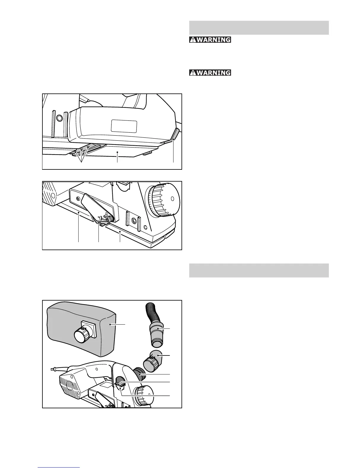
Dust extraction
The standard equipment for the planer in-
cludes devices to enable the planer to be
used with both the chip collecting bag (5.1)
(accessories) (488 566) or a suction hose
(5.2) (accessories) connected to a dust ex-
tractor.
The connector for dust extraction can be
fi tted on either side of the tool. To change
sides, press the toggle lever (5.5) down
fi rmly. This releases the lug on the outer
edge of the casing and the adapter (5.4)
can be pushed through the casing.
The adapter can now be inserted into the
casing opening (5.6) lug fi rst up the stop in
the casing.
Either the chip collecting bag (5.1) or an
angle piece (5.3) for a suction hose adapter
(5.2) can be fi tted to the adapter (5.4). The
chips can be defl ected in any direction by
turning the angle piece.
3.33.23.1
4.34.24.1
5.2
5.3
5.4
5.5
5.6
5.1