9
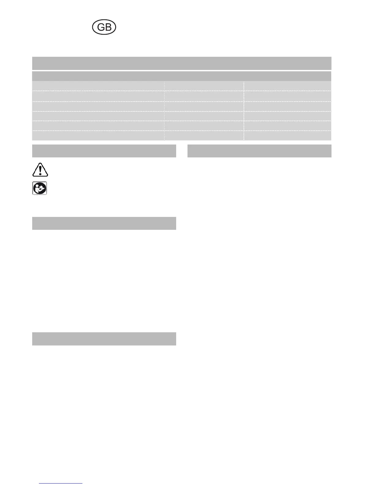
1 Technical data
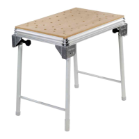
MFT/3 MFT/KAPEX
Bench dimensions (width x length) 1157 x 773 mm 869 x 581 mm
Bench height - with foldaway legs 900 mm 790 mm
- without foldaway legs 180 mm 180 mm
max. working width 700 mm -
max. workpiece thickness 78 mm -
Weight 28 kg 18 kg
5 Setting up and attaching
Accessory attachments can be secured at differ-
ent points on the multifunction table to enable
different working positions.
In the standard working position, the user stands
along one side of the bench [Fig. 2]. In these op-
erating instructions, this side of the bench is re-
ferred to as the "front".
5.1 Setting up
Screw on the knobs [2-3] until the stop is reached.
Unfold the foldaway legs and tighten the knobs
on the joints to secure. Turn the end cap [2-1] on
the right to adjust the length of the leg and com-
pensate for an uneven fl oor surface.
The corner feet [2-4] are fi tted with rubber caps
so that the bench stands securely when the legs
are folded away.
5.2 Attaching the guide rail
Stops [3-1/4-4] are attached to the longitudi-
nal profi le on the front and back of the bench ex
works for the recommended working position.
The swivel unit [1-4/3-2] is secured to the longi-
tudinal back edge and the support unit [1-2/2-2]
to the longitudinal front edge.
Unscrew the height adjustment clamp [4-3] and
the rotary knob [4-1], slide the units along the
profi led groove from the left up to the stop and
then tighten the rotary knob [4-1] again to se-
cure. To eliminate play, you can adjust both units
in the profi led groove by turning the adjusting
screws [4-2] in the guide spring using a size 2.5
Allen key.
To make both units more accessible, lift the metal
plates all the way up and push down the clamp-
ing lever [4-3] to secure in position. If required,
you can adjust the screws [4-2] to increase the
clamping effect.
Multifunction table
MFT/3, MFT/KAPEX
2 Symbols
Warning of general danger
Read the Operating Instructions/Notes!
The specifi ed illustrations are at the beginning of
the Operating Instructions.
3 Scope of delivery
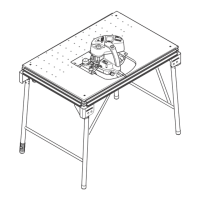
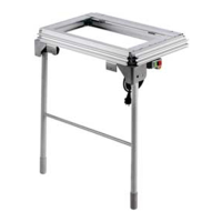
[1-1] Bench consisting of: profi le frame, cor-
ner feet, perforated top, foldaway legs
MFT/3 only
[1-2] Support unit
[1-3] Guide rail FS 1080
[1-4] Swivel unit
[1-5] Pre-set profi le setting rail and
[1-6] Stop ruler
[1-7] Additional clamp for stop ruler
[1-8] Stop fl ag MFT/3-AR
[1-9] Defl ector
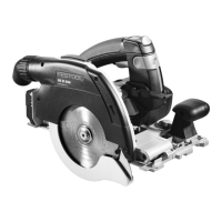
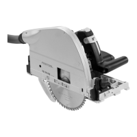
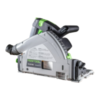
4 Intended use
The multifunction table MFT/3 is designed for
safe, accurate sawing and routing in combina-
tion with Festool electric power tools.
The clamping systems included in the acces-
sories programme enable the user to attach
workpieces securely to the worktop. The base
becomes a work bench for various tasks such as
planing, sanding, carving, etc.
The multifunction table MFT/KAPEX was spe-
cially designed for attaching the KAPEX KS 120/
KS 88.
The user bears the responsibility for damage and
accidents caused by improper use.
 Loading...