3
Electrical Configuration and Heating Efficiency
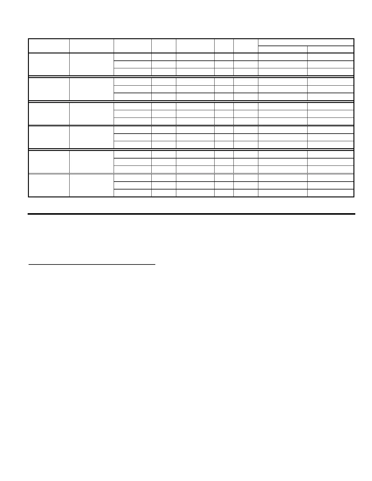
Heater Voltage Amp. Hourly Heating Capacity (gallons)
Model Configuration Connection Phase Wires KW draw Cold Water * Hot Water **
HWB-5 (-1) 1 X 3000 watt 120/208 1 ph. 3 + ground 2.4 11.3 5.6 12.9
120/220 1 ph. 3 + ground 2.7 12.4 6.5 14.9
120/240 1 ph. 3 + ground 3.1 13.0 7.4 17.2
HWB-10 (-1) 2 X 3000 watt 120/208 1 ph. 3 + ground 4.6 22.1 11.2 25.8
120/220 1 ph. 3 + ground 5.3 24.2 12.9 29.9
120/240 1 ph. 3 + ground 6.1 25.5 14.9 34.3
HWB-15 (-1) 2 X 3000 watt 120/208 1 ph. 3 + ground 4.6 22.1 11.2 25.8
120/220 1 ph. 3 + ground 5.3 24.2 12.9 29.9
120/240 1 ph. 3 + ground 6.1 25.5 14.9 34.3
HWB-15 (-2) 3 X 3000 watt 120/208 3 ph. 4 + ground 6.9 19.2 16.7 38.6
120/220 3 ph. 4 + ground 7.9 21.0 19.4 44.8
120/240 3 ph. 4 + ground 9.1 22.2 22.3 51.5
HWB-25 (-1) 6 X 3000 watt 120/208 3 ph. 4 + ground 13.6 38.0 33.5 77.3
120/220 3 ph. 4 + ground 15.8 41.6 38.8 89.6
120/240 3 ph. 4 + ground 18.1 43.8 44.6 103.0
HWB-25 (-2) 6 X 4000 watt 120/208 3 ph. 4 + ground 18.1 50.5 44.6 103.0
(special order)
120/220 3 ph. 4 + ground 21.0 55.3 51.8 119.5
120/240 3 ph. 4 + ground 24.1 58.2 59.5 137.4
Installation
(For Qualified Service Technicians Only)
Keys To A Successful Installation
FETCO dispensers are rugged and reliable machines that will provide many years of service. However, if not
installed correctly by qualified personnel, the unit will not operate properly and damage may result. Damages resulting
from improper installation are not covered by the warranty.
Here are the key points to consider before installation:
Electrical: All FETCO dispensers require NEUTRAL. Ground is not an acceptable substitute. Installation
without neutral will almost certainly cause damage to the electronic components.
The power connection to L1 on the terminal block must be at least 105 volts. Less than 105 volts will cause
erratic behavior.
The power switch has a built-in circuit breaker. To reset it, turn to the “off” position, and then back to the “on”
position.
The electrical drawing for the dispenser is located on the inside of the cover.
Plumbing: This equipment is to be installed to comply with the applicable federal, state, or local plumbing codes.
The water line must be flushed thoroughly prior to connecting it to the dispenser to prevent debris from
contaminating the machine.
Verify that the water line will provide at least 2 gallons per minute before connecting it to the dispenser.
General: Utilize a qualified beverage equipment service technician for installation.
Do not adjust the thermostat settings unless absolutely necessary. They are set at the factory for optimum
performance.
 Loading...