4
Installation Check List
The installation must comply with applicable federal, state, and local codes having jurisdiction at your location. Check
with your local inspectors to determine what codes will apply to the installation and operation of FETCO products.
1. Review the Dimensional Drawings (page 5) and the Operating Procedures (page 6) for the unit you are installing.
Verify the dispenser will fit in the space intended for it. Verify that the counter or table will support the weight of
the dispenser when filled.
2. Verify that the actual voltage at the electrical service connection is compatible with the specifications on the
dispenser’s serial number plate. Make sure the electrical service includes neutral. Refer to the "Electrical
Configurations " section, (page 3) to determine how the dispenser will perform on other voltages. Ensure at this
time that the circuit breaker to the dispenser and the power switch on the dispenser are in the off position
3. The thermostat and the water tank fill level are pre-set at the factory. There is no need to turn off the heaters
during the installation process. The heaters are disabled by the liquid level control board until water is sensed.
The heating process will start automatically when the tank has filled with water
5. Place the dispenser on a suitable counter or stand, ensuring it is strong enough. Refer to the dispenser weights
and capacities chart (page 2) for dry and wet weights.
6. When the dispenser is in position for use, level the dispenser front to back as well as side to side by adjusting
the feet.
8.
Remove the cover.
9.
Water connection:
• Water inlet is a 3/8 inch compression fitting on HWB-25, 1/4 inch compression fitting on all other models.
• The dispenser can be connected to a cold or hot water line. Cold water is preferred for best flavor, but hot
water will allow for faster recovery times.
• Install a water shut off valve near the dispenser to facilitate service. If an in-line water filter is used, it should
be installed after the water shut off valve and in a position to facilitate filter replacement.
• Flush the water supply line and filter before connecting it to the dispenser.
• Verify that the water line will provide at least 2 gallons per minute and that the water pressure is between 20
and 75 psig.
• Use a wrench on the factory fitting when connecting the incoming water line. This will reduce stress on the
internal connections and reduce the possibility of leaks developing after the installation has been completed.
10.
Vent tube connection:
• Vent tube connection is a 3/8 inch hose barb.
• The end of the vent tube should be open to the air, not connected or submerged.
11.
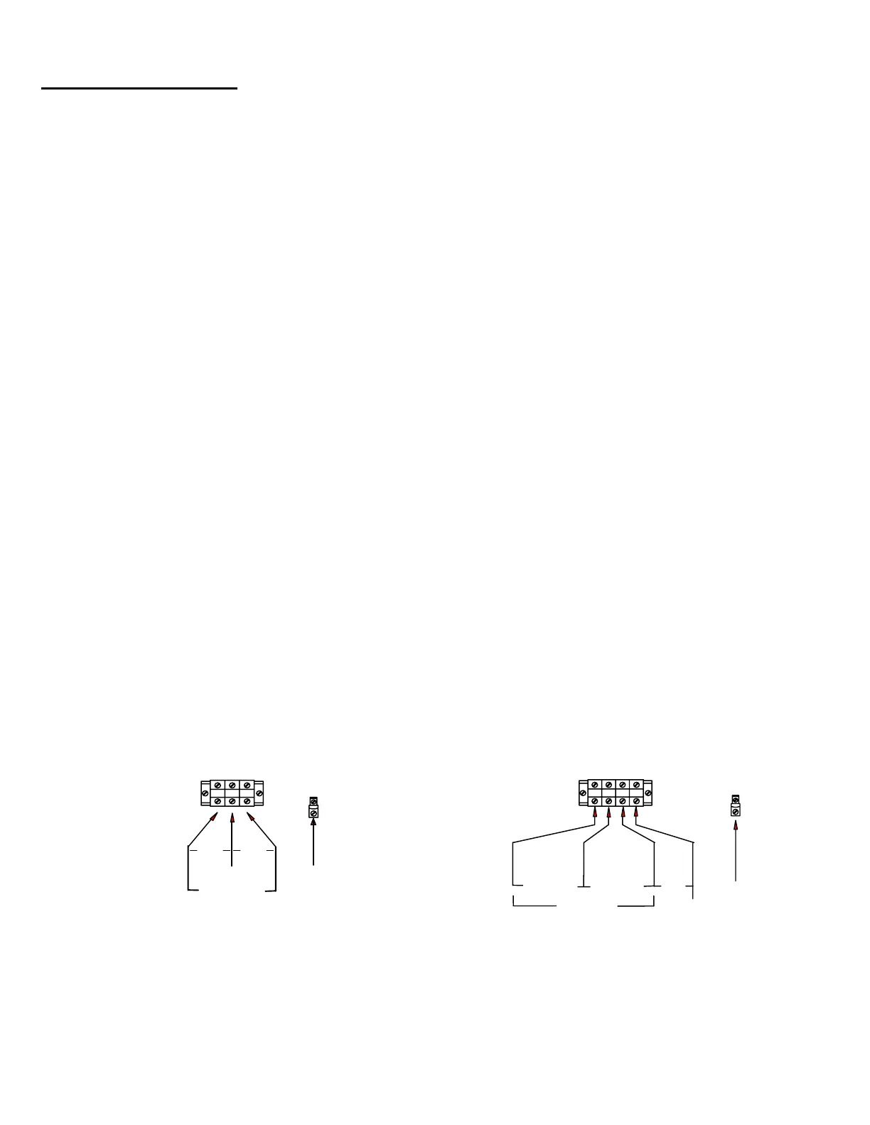
Power connection:
• A fused disconnect switch or circuit breaker on the incoming power line must be conveniently located near
the dispenser, and its location and markings known to the operators.
• All dispensers require neutral. Damage to the dispenser may result if neutral is not present.
• The body of the dispenser must be grounded to a suitable building ground. A ground lug is provided in the
dispenser next to the power terminal block. Use only 10 gauge copper wire for grounding.
• Electrical connections must be secured in-place within the unit to meet national and local standards.
L1
L2
N
GROUND LUG
GROUND
WIRE
SINGLE PHASE
TERMINAL BLOCK
N
208-240V
120V 120V
3 PHASE
TERMINAL BLOCK
GROUND LUG
GROUND
WIRE
L1
L2
L3
N
N
120V
208-240V 208-240V
208-240V
Domestic Electrical Configurations
 Loading...