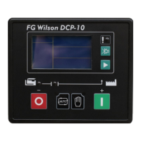
DCP-10
Page 6/27
4. Installation Guide
4.1 The cutout dimensional drawing installed on panel as above attached.
The controller is fixed by 2 special fittings. The shock-proof equipment must be mounted if the
enclosure is mounted on Genset or other heavy vibrant device. A readily accessible disconnect
device shall be incorporated external to the equipment.
4.2 Please refer to the above Typical Wiring Diagram 2.3 for connection.
4.3 Installation of engine LOP and HET sensors:
1211
Terminal
12
Battery negative (Genset enclosure)
11
Description
Sensor Com. Port
HET sensor/ temp switch
LOP sensor/ LOP switch
DCP-10
C O N T R O L L E R
CAUTION:
Pin no. “11” and “12” is for “LOP sensor or switch signal” and “HET
sensor or switch signal” input respectively. Either switch or sensor can be
chosen. When sensor is used, according to the actual situation, increase
the cross section area of cable to reduce the cable resistance from
controller to engine, which ensures the accuracy of measured values for
both oil pressure and engine temperature.
If both switches and sensors are required for oil pressure and engine
temperature, connect Pin no. “11” and “12” as above, and connect 2
configurable inputs to the switches of oil pressure and temperature, then
configure parameters by setting.
 Loading...