Do you have a question about the FG Wilson DCP-10 and is the answer not in the manual?
Explains the meaning of the warning symbol and its potential consequences.
Explains the meaning of the caution symbol and its potential consequences.
Explains the meaning of the note symbol for additional information.
Details the physical size and panel cutout dimensions for the controller.
Lists and describes the function of each terminal pin on the controller.
Illustrates the complete wiring connections for the controller and associated components.
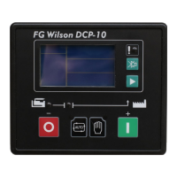
Explains the function of each button and LED on the controller's front panel.
Provides instructions for physically mounting the controller and installing engine sensors.
Describes how to switch between AUTO and MANUAL operating modes.
Outlines the step-by-step process for starting and running the genset in AUTO mode.
Explains conditions leading to start failure and the sequence for generator shutdown.
Details the procedure for starting and stopping the genset in MANUAL mode.
Describes start and stop sequences for N.O. and N.C. fuel solenoids.
Explains the configuration and operation of idle and preheat functions.
Visual representation of the genset start and stop process timing.
Lists and explains pre-alarm conditions, their indicators, and LCD displays.
Details further pre-alarm states like over current, over/under voltage, and low fuel level.
Lists and explains shutdown alarm conditions, their indicators, and LCD displays.
Provides a table of failure codes and important operational notes for alarms.
Details settings for system-wide parameters like CT/VT ratio and voltage.
Covers parameter settings related to generator voltage, frequency, and current.
Details configurable parameters for engine operation, such as speed and temperature.
Explains the configuration options for digital inputs and relay outputs.
Outlines parameters for calibrating sensor offsets and voltage readings.
Lists available brands and models for pressure and temperature sensors.
Details functions that can be assigned to configurable inputs.
Details functions that can be assigned to configurable outputs.
Shows examples of static data displayed on the LCD screen.
Explains how to access and modify controller parameters using the menu system.
| Brand | FG Wilson |
|---|---|
| Model | DCP-10 |
| Category | Controller |
| Language | English |