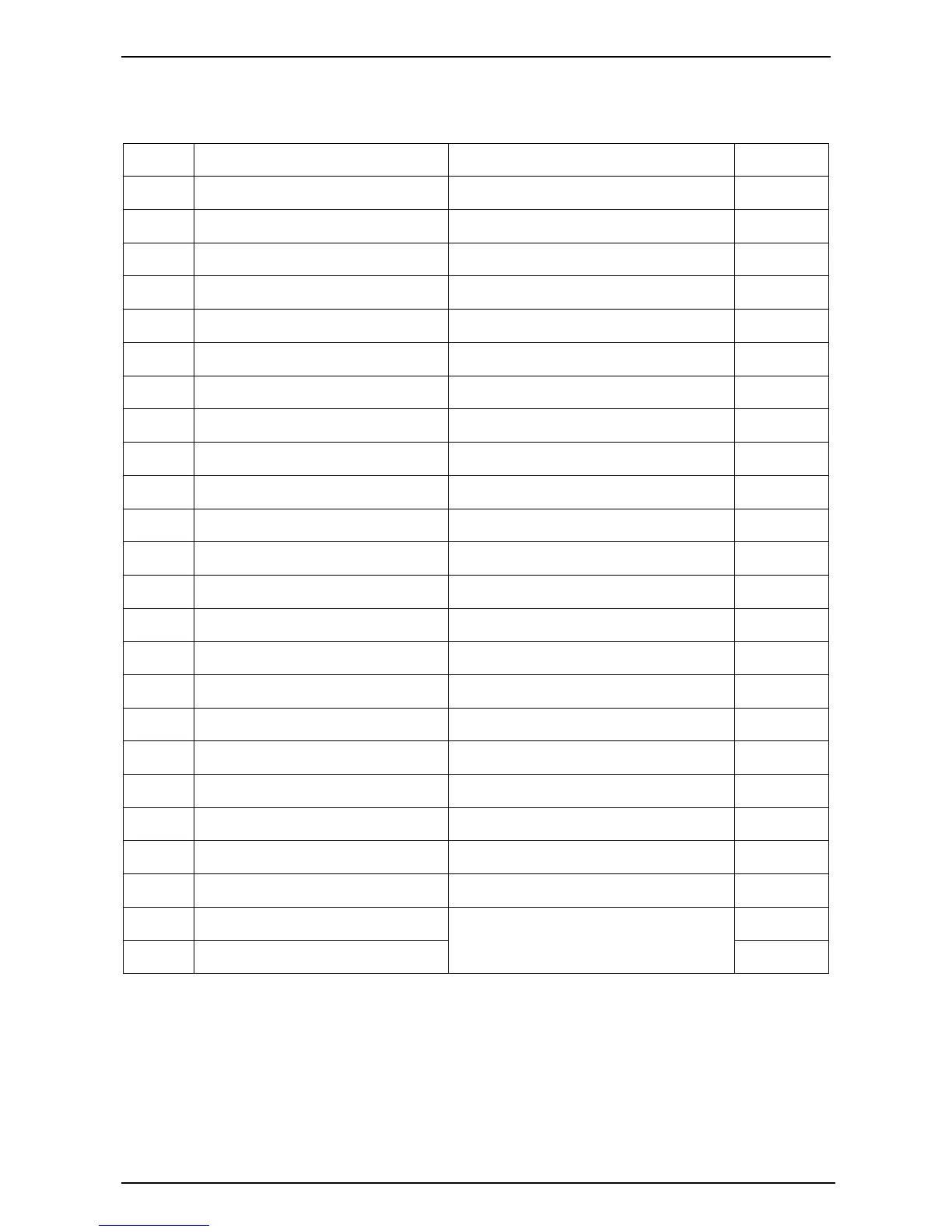
Function Description Signal Dim
1
GEN. V
L1-N
input 0-300Vac
1mm²
2
GEN. V
L2-N
input 0-300Vac
1mm²
3
GEN. V
L3-N
input 0-300Vac
1mm²
4
GEN. Neutral
1mm²
5
Not used
6 Not used
7 I1 Gen current input 0-5A
2.5mm²
8 I2 Gen current input 0-5A
2.5mm²
9 I3 Gen current input 0-5A
2.5mm²
10 Common port for current input 0-5A
2.5mm²
11 LOP sensor or switch signal LOP sensor (<2KΩ)
1mm²
12 HET sensor or switch signal HET sensor (<2KΩ)
1mm²
13 Configurable digital input signal 1 low level is active
1mm²
14 Configurable digital input signal 2 low level is active
1mm²
15 Configurable digital input signal 3 low level is active
1mm²
16
Charge excitation power output if not used, do not connect to negative
1mm²
17
Configurable relay output 1 N.O. contact, 3A/30Vdc
1mm²
18
Configurable relay output 2 N.O. contact, 3A/30Vdc
1mm²
19
Configurable relay output 3 N.O. contact, 3A/30Vdc
1mm²
20
+5V supply Max 100mA,
1mm²
21
Start (Crank) relay output N.O. contact, 3A/30Vdc
1mm²
22
Fuel solenoid relay output N.O. contact, 3A/30Vdc
1mm²
23
Battery supply (+B)
1mm²
24
Battery supply (-B)
12V/24V (8-35Vdc continuous)
1mm²
 Loading...