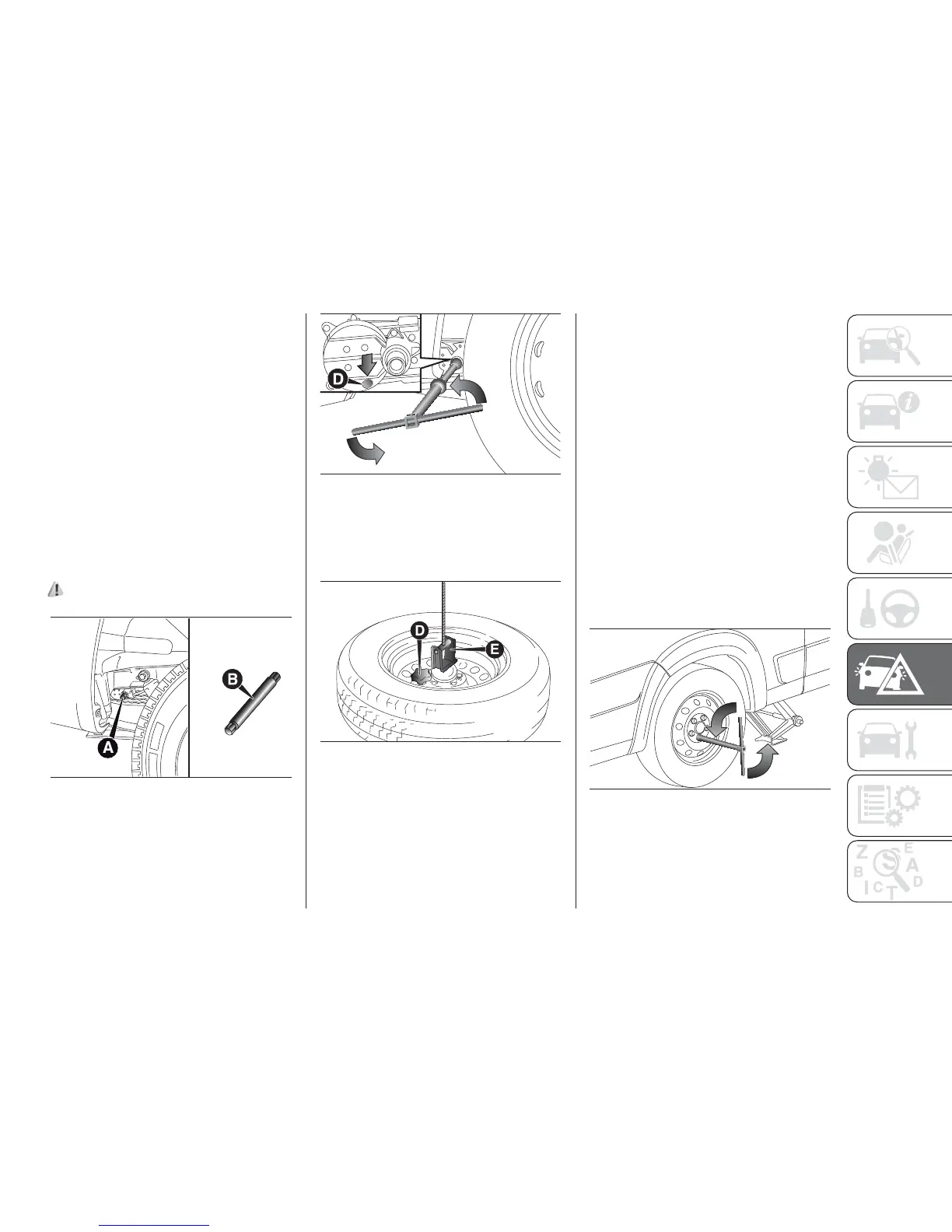
After lifting the vehicle:
❒ for all versions, when gaining access
through the vehicle's right rear wheel
arch, adjust the screw A fig. 185
for the spare wheel retaining device,
using the spanner provided and
correctly assembled, with the
dedicated extension Bfig. 185;
❒ turn tool C anticlockwise fig. 186 to
allow the spare wheel to be lowered;
❒ continue turning anticlockwise until
the stop point, indicated by the
stiffening of the manoeuvre or a click
from the clutch present in the device;
153) 154)
❒ after unwinding the whole cable of
the spare wheel lifting device, remove
the wheel from the vehicle;
❒ unscrew the retaining knob D fig. 187
and release the wheel releasing the
support E.
❒ with the assembled tools, completely
loosen the bolts fig. 188 and remove
the wheel;
❒ fit the spare wheel, aligning holes G
fig. 189 with the pins H. When fitting
the spare wheel, ensure that the
wheel support surfaces are clean and
free of impurities that could
subsequently cause the bolts to
loosen;
❒ screw in the 5 fastening bolts;
❒ assemble the tools to fully tighten the
bolts, passing alternately from one
bolt to the one diametrically opposite,
following the order illustrated in fig.
189;
❒ use the wheel removal wrench to
lower the vehicle and remove the
jack;
185
F1A0171
186
F1A0421
187
F1A0174
188
F1A0422
205