At the end of the operation:
❒ take the removed wheel, re-attach it
to the mount E fig. 187 and tighten
the knob D;
❒ introduce the assembled tool fig. 186
with the suitable extension B fig. 185
on the screw A fig. 185 of the spare
wheel housing manoeuvring device
and turn clockwise to lift the spare
wheel back up until it is fully
supported in its housing under the
platform, checking that the
attachment reference D fig. 186
appears in the window on the device;
155)
For vehicles with alloy rims, proceed as
follows:
❒ carry out the above described
operations for changing the wheel
until loading the punctured wheel on
the spare wheel lifting device;
❒ take the kit from the tool bag, located
in the glove compartment;
❒ the kit includes one bracket, three
special screws and one Allen
spanner, 10 size;
❒ go to the rear side of the vehicle
where the spare wheel is located;
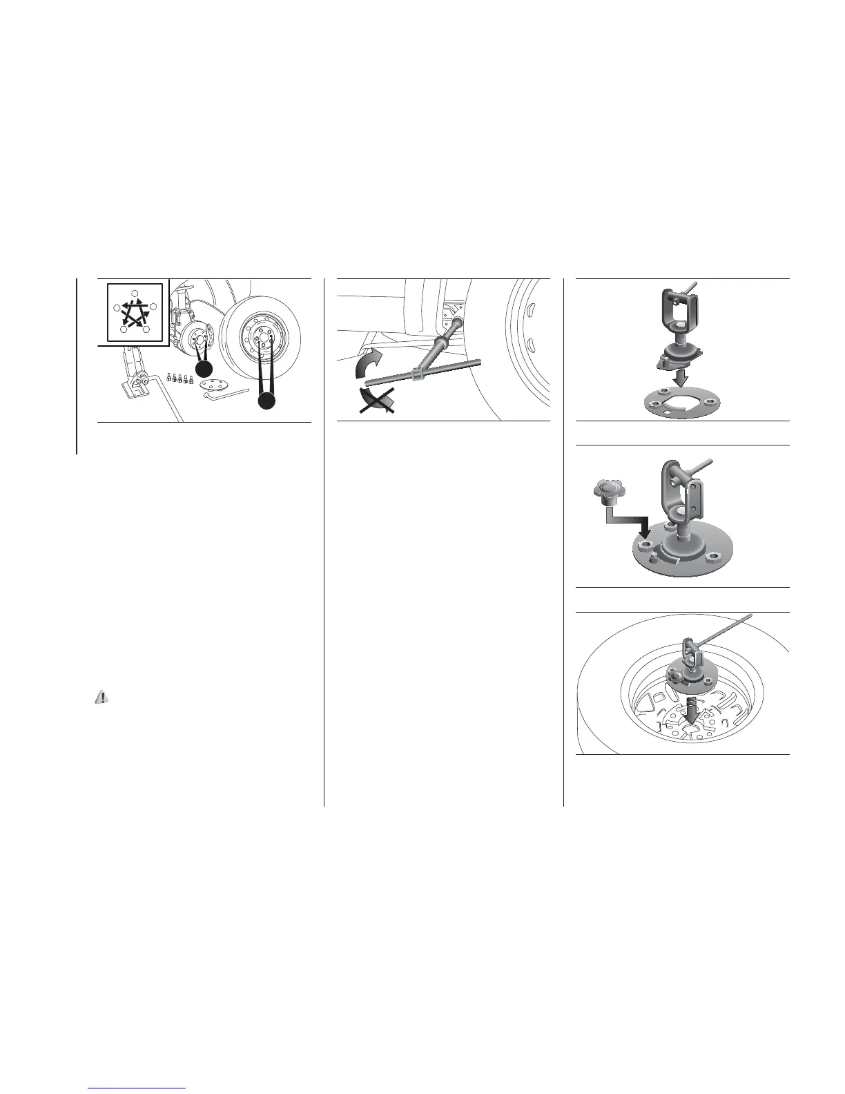
❒ make sure to have fully unwound the
cable of the spare wheel lifting
device; take the bell and position it
inside the circular bracket fig. 191;
❒ tighten the knob on the screw to
secure the bracket fig. 192.
❒ lay the bracket on the inside of the
alloy rim fig. 193.
❒ use the Allen spanner and tighten the
three special screws on the nuts of
the bracket fig. 194 locking the rim;
G
H
189
F1A0176
190
F1A0430
191
F1A0424
192
F1A0425
193
F1A0426
206
IN AN EMERGENCY