BOOK0795-F
5
Signal wiring refers to wiring for potentiometers, tachometer generators, and transducers. Control wiring
refers to wiring for operator controls. Signal and control wiring may be run in a common conduit, but not
in the same conduit with the power wiring. In an enclosure, nonshielded signal and control wiring must be
kept separated from power wiring and only cross at 90 degree angles.
If shielded wire (such as Alpha 2422 - two conductor, 2423 - three conductor, 2424 - four conductor) is
used for the signal and control wiring, connect the shields to chassis ground (ground screw on the control-
ler base) and tape the opposite ends of the shields.
Two 3/4-14 NPT threaded holes are provided for conduit entry, one each in the top and bottom of the con-
troller base.
9. OPTIONS - This equipment manual is for use with the basic controller. If options are installed in the con-
troller, they will be identified on the controller data label. The instruction sheets supplied with the options
should be reviewed before the controller is installed.
INSTALLING THE CONTROLLER
1. Remove the controller front cover (if used) by removing the four cover screws.
2. Check components in the controller for shipping damage. Report shipping damage to the carrier.
3. Check the controller and motor data labels to be sure the units are electrically compatible.
4. Be sure the controller has been calibrated correctly for the motor being used. Calibration is performed by
changing the position of a Jumper (J4) on the controller control board to comply with Table 3. To change
the position of Jumper J4, pull the jumper from the control board and then push it onto the appropriate two
pins on the board. For the location of J4, see Figure 22 (page 43) or Figure 23 (page 44) as applicable.
5. Check the positions of Jumpers J1, J2, and J3 on the control board. For the locations of J1, J2, and J3, see
Figure 22 (page 43) or Figure 23 (page 44) as applicable. For a 230 VAC line supply and a 180V armature
motor, Jumper J1 must be in the 230V position, and Jumpers J2 and J3 must both be in the 180V position.
For a 115 VAC line supply, J1 must be in the 115V position, and J2 and J3 must be in the 90V position.
NOTE: If Option 1001 (Armature Contactor, Unidirectional), 1004 (Armature Contactor, Reversing), or
1775 (Signal Interface) is to be installed in the controller, do not offset the five-position plug
(supplied with the option) at Connector J1 on the control board. Do not confuse Connector J1
with Jumper J1. Refer to the Instruction Sheet (ISP0703, ISP0666, ISP0653, respectively) sup-
plied with the option for connection instructions.
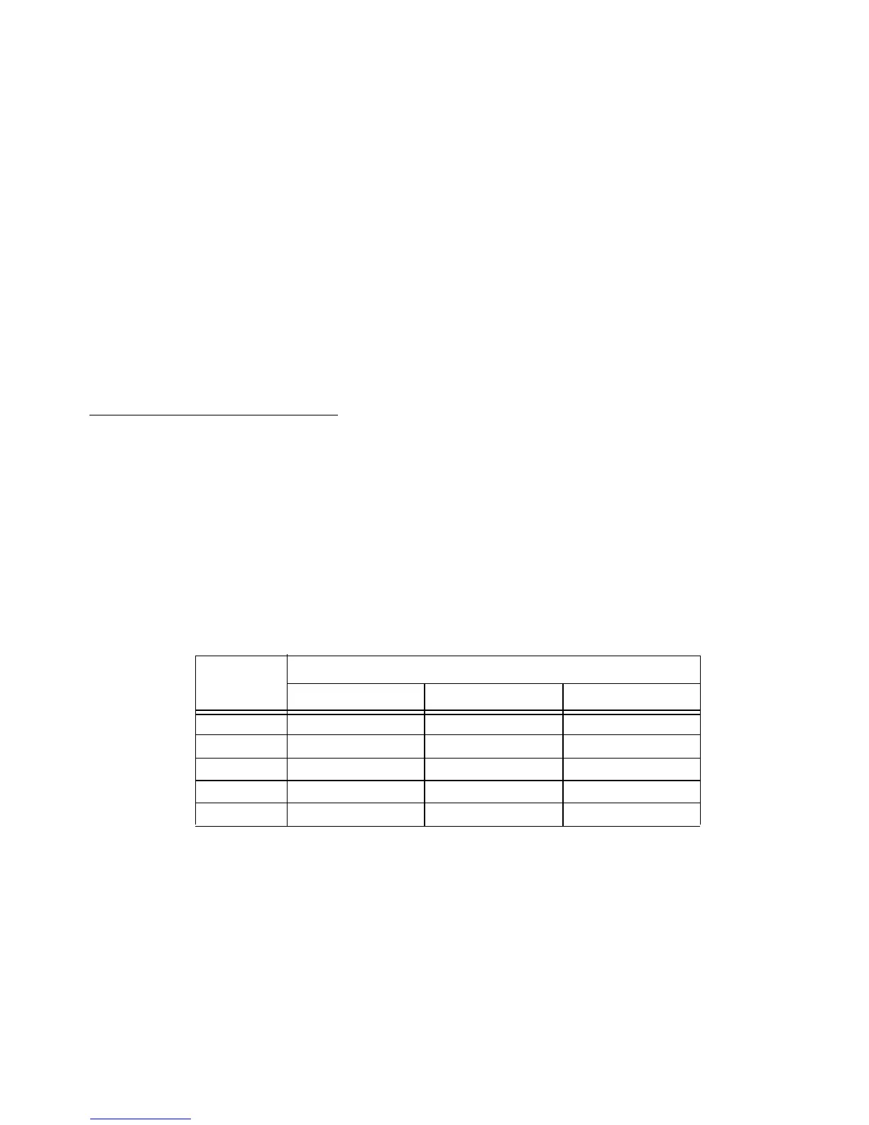
TABLE 3. JUMPER J4 POSITIONS
JUMPER
POSITION
MOTOR ARMATURE CURRENT RATING (AMPERES)
a
a. Select the position closest to the motor nameplate armature current rating.
2 HP Maximum 3 HP Maximum 5 HP Maximum
100% 10 15 25
80% 8 12 20
60% 6 9 15
40% 4 6 10
20% 2 3 5
 Loading...