BOOK0795-F
6
MODEL 2601 and 2602 CONTROLLERS
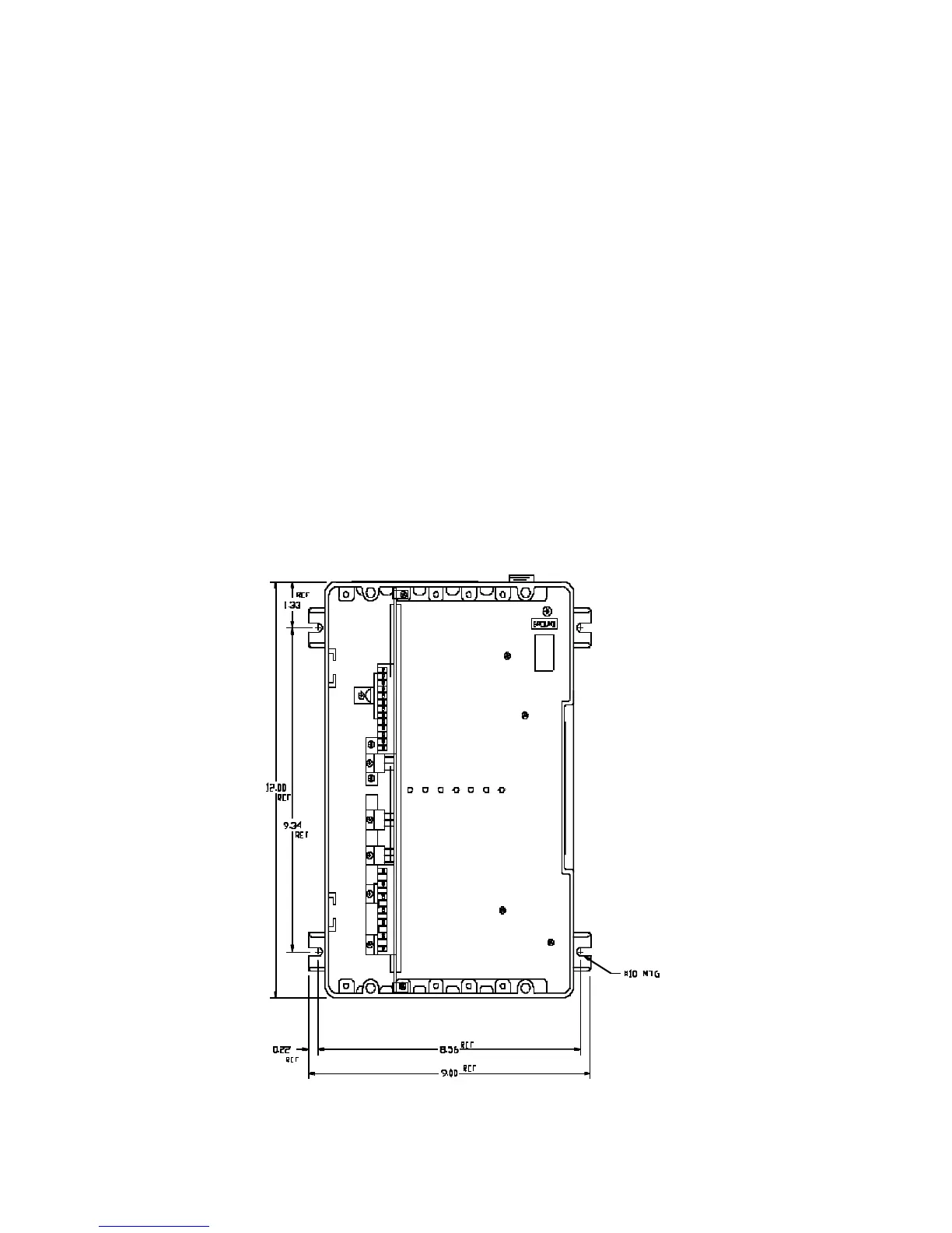
1. Mount the controller. Mounting dimensions are shown in Figure 1, below.
2. Install conduit and connect the power wiring to Terminals L1, L2, A1 (+), A2 (-), F+ and F-. Be sure to
observe Installation Guidelines 5 and 8 on pages 4 and 5. If half-wave shunt field voltage is desired, con-
nect one of the motor shunt field leads to Terminal F/2 (see Table 14 on Page 37).
NOTE: Low inductance motors require a full-wave field to prevent current instability.
3. If the controller contains any options that require external wiring, follow the wiring instructions in the
instruction sheet supplied with the option.
4. If remote operator control wiring and/or signal wiring is required, connect the controller as shown in the
appropriate connection diagram (Figures 4 through 18). Figures 4 through 9 show operator control connec-
tions, and Figures 10 through 18 show signal connections.
5. Set the DIP Switch (S3) as shown in the appropriate connection diagram. See Figure 22 (page 43) or Fig-
ure 23 (page 44), as applicable, for the location of DIP Switch S3. Also refer to Table 13, “DIP Switch Set-
tings,” page 36.
6. Install the controller cover, if used.
FIGURE 1. CONTROLLER MOUNTING DIMENSIONS, MODELS 2601 AND 2602
 Loading...