- 1 4 -
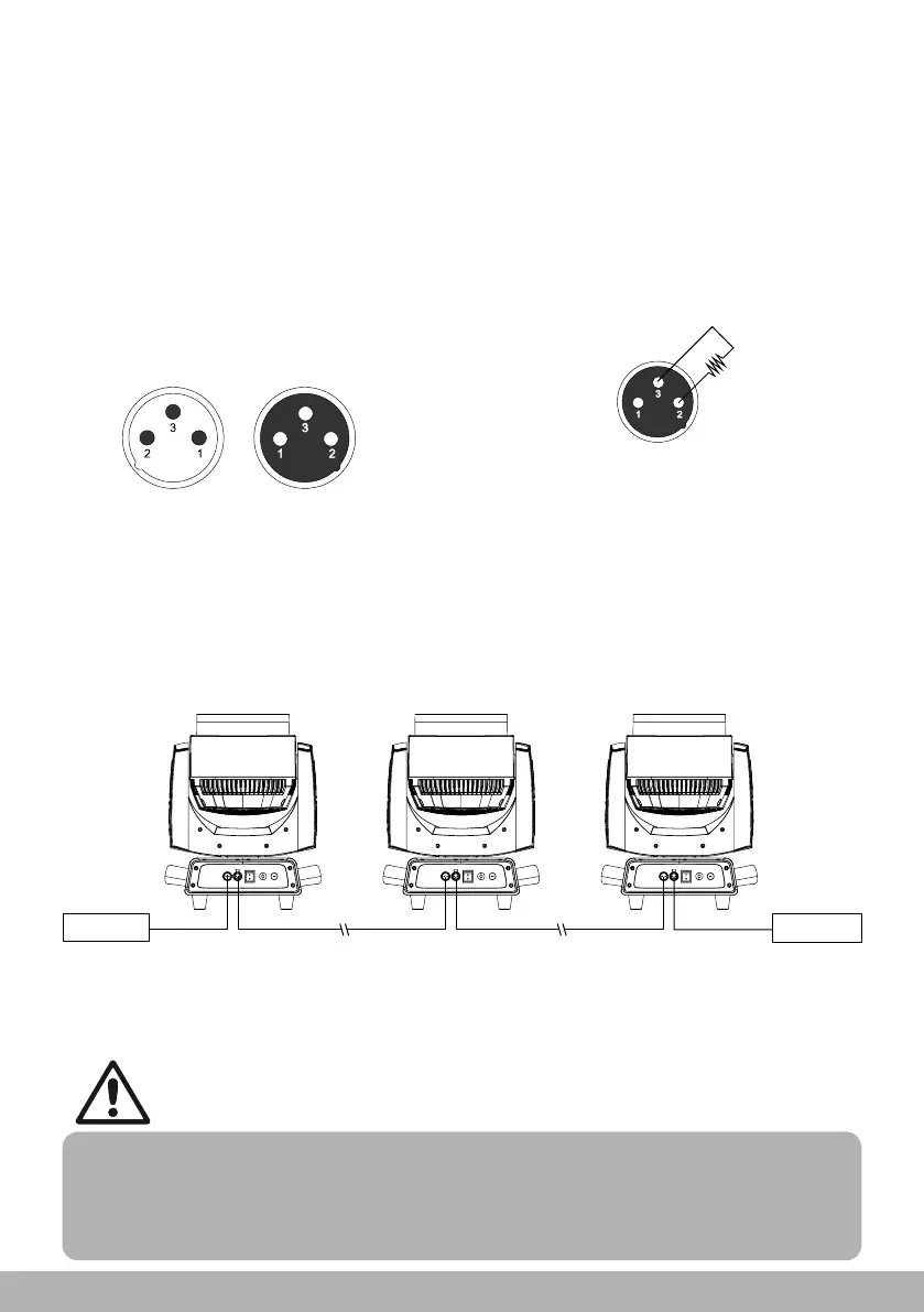
3-pin XLR connector
Pin1: GND
Pin2: Signal(-)
Pin3: Signal(+)
Terminator
Terminator specification: a
120Ω plug-in resistor with
rated power of 0.25W,
soldered between pin 2 and
pin 3 at the end of respective
data link.
Fig.(8.3-1)
DMX connection
Note: The signal cable was type X connection.
Type X connection—if the external flexible cable or cord of this fixture is damaged, it
shall be replaced by a special cord or cord exclusively available from the manufact-
urer or his service agent.
3-pin or 5pin XLR connecters are provided for fixture DMX input and output. Pin 1 is
for earthing, pin 2 is for minus signals, and pin 3 is for plus signals. To prevent and
absorb the reflection and interference of the signals, each data link must be ended
by a respective terminator.
1. No more than one signal input or output can occur in one fixture.
2. Don’t split a data link via output ports on the fixture, use a DMX512 signal amplifier instead,
if necessary.
3. Use only shielded-pair cables, and standard microphone cable is not reliable for
long-distance data transfer.
Notice!
If long-distance data transfer occurs, a DMX512 signal amplifier is necessary. The
added amplifier is inserted between the lighting controller and the first fixture on the
basis of a normal data link.
Note: Make sure the fixture vertically upwards when it is placed horizontally, the
safe distance between two adjacent fixtures must be ≥ 500mm.
Fig.(8. 3-2)
Terminator
Controller
Input Output Input Output
OutputInput
Connect the fixtures with Max.5 pieces. Make sure to insert the “signal in” terminal
in the last connecting fixture. shown in Figure8.3-2.