(1) CLAMP. Opens 2.04 inche
s
(52mm) to enclose
conductors.
(2) HOLD. Freezes reading in digital display.
(3) DISPLAY. Liquid crystal display.
(4) RANGE. Selects 0 to 40A, 0 to 400A, or AUTO.
(5) ON OFF. Selects meters power ON or power OFF.
(6) . Selects continuity testing mode.
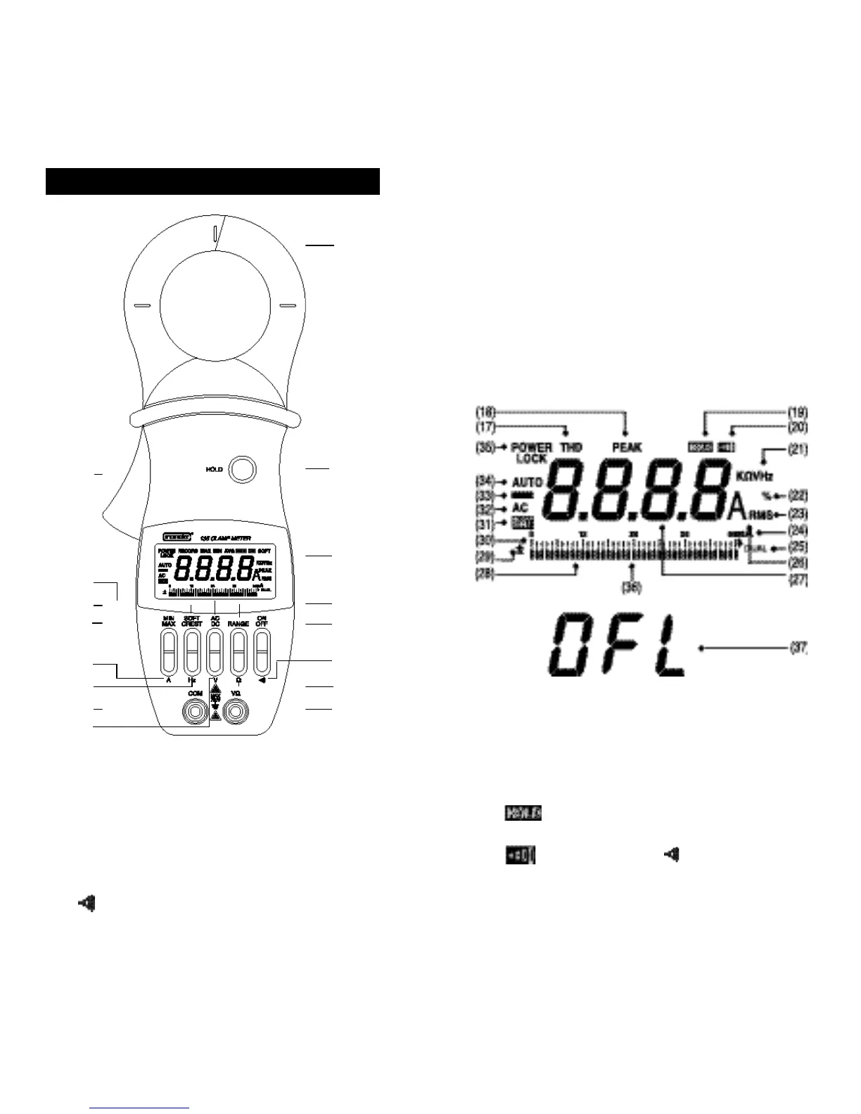
3. Explanation of Controls and Indicators
54
(1)
(3)
(4)
(11)
(9)
(10)
(12)
(5)
(6)
(8)
(7)
(2)
(12)
(13)
(15)
(16)
(14)
(7) Ω . Selects ohms measurement mode.
(8) VΩ . Volt, Ohms, Continuity Test Input Terminal.
(9) V. Selects volts measurement mode.
(10) COM . Common Terminal.
(11) Hz . Selects frequency measurement mode.
(12) A . Selects amperes measurement mode.
(13) MIN MAX . Selects RECORD mode and displays
recorded MAX, MIN, and AVG.
(14) SOFT CREST . Selects SOFT for a runn
i
ng 3-second
average, or CREST for ha
l
f cycle peak amperes.
(15) AC DC . Selects AC or DC mode.
(16) LEVER . Opens and closes clamp jaws.
(17) RECORD . Displayed (blinking) when MAX, MIN, and
AVG values are being recorded. Duration of
RECORD is limited by battery life.
(18) MAX MIN AVG . Displayed in RECORD mode by
pressing MIN MAX pushbuttons.
(19) . Displayed when HOLD pushbutton has been
pressed.
(20) . Displayed when pushbutton has been
pressed.
(21) SOFT .
D
isplayed when current flow readings or Hz or
V readings are softened out over 3-second interva
l
s
.