10. To record read
i
ngs and to view maximum, minimum,
and average values, press the MIN MAX pushbutton.
11. To clear RECORD, press the MIN MAX pushbutton for
2 seconds.
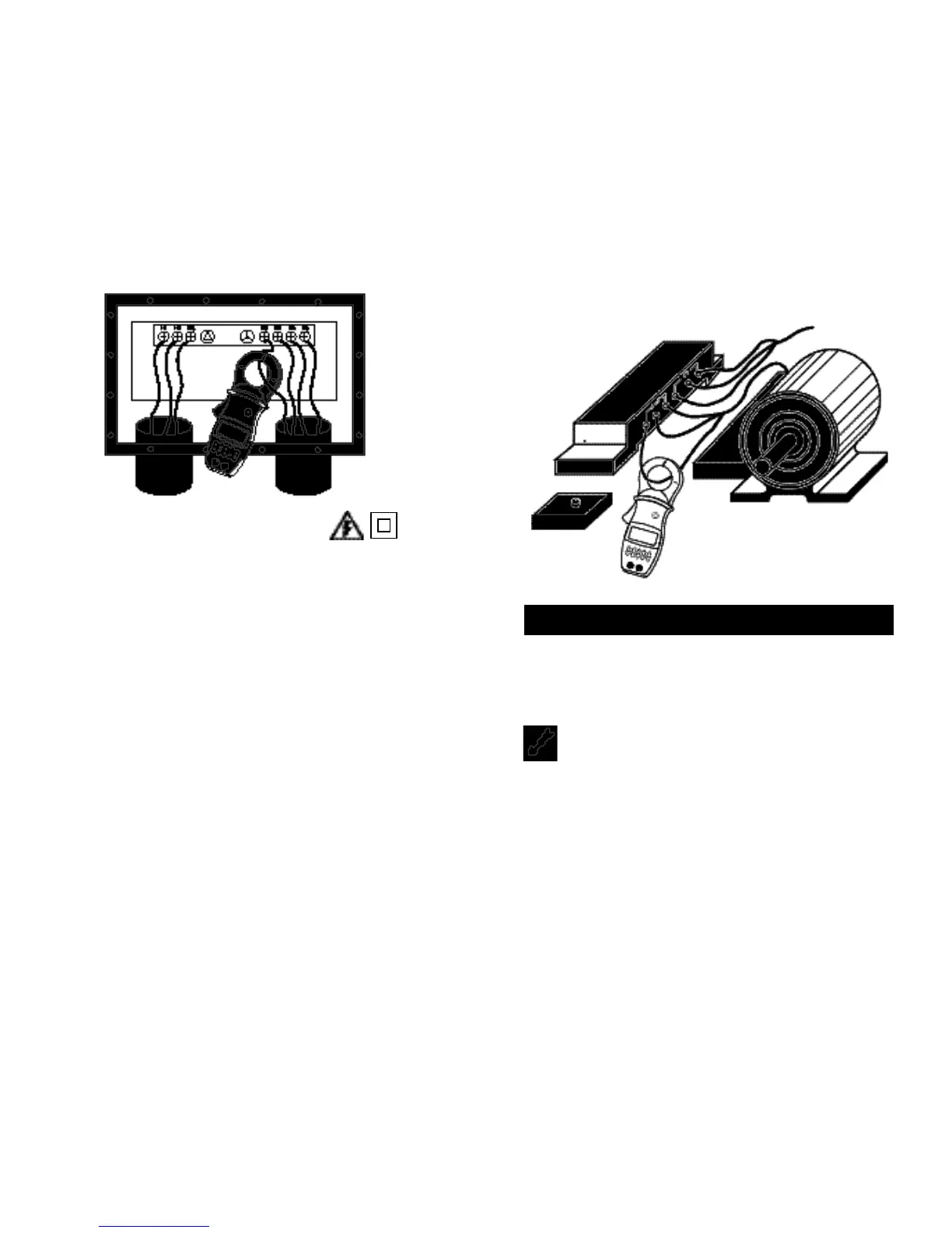
6.5 Adjustable Speed Motor Controllers
You can measure input current, output current and
frequency of the adju
s
table speed motor controllers. The
output current frequency is used to ca
l
c
ulate the rotat
i
ng
speed of the motor, while input current frequency is used to
measure the frequency of the power line. The frequency of
the output current is important because the
v
oltage
frequency is often mean
i
ngless for the ca
l
c
ulations of
motor controller speed.
1. Press the ON OFF pushbutton to turn on this Meter.
2. Clamp around an input or output phase (as required),
and run motor at desired
s
peed. Be sure the clamp
jaws are securely closed, or measurements will not be
accurate.
3. Observe the display for true-rms current flow.
4. Measure an output phase of the motor controller and
use Hz mode to measure frequency. Nominal motor
speed is calculated from RPM = 120F/P, where F is
the frequency measured, and P is the number of motor
poles.
26 27
5. To record readings and to view readings, pres
s
the
MIN MAX pushbutton.
6. To clear RECORD, press the MIN MAX pushbutton for
2 seconds.
7.1 Maintenance
Repairs or servicing should only be performed by qualified
personnel.
WARNING!
TO AVOID ELECTRIC SHOCK, DO NOT PERFORM ANY
SERVICING PROCEDURE UNLESS YOU ARE
QUALIFIED TO DO SO. READ “CLAMP-ON METER
SAFETY” AT THE BEGINNING OF THIS MANUAL
BEFORE PROCEEDING.
To assure continued safety of this Meter, inspect this Meter
before use for cracks or missing portions of the insulating
cover, or for
l
oose or weakened components. Pay
particular attention to the insulation surrounding the clamp
jaws and clamp lever. Any Meter that fails this inspection
should be made inoperative by taping the clamp shut.
7. Maintenance and Calibration
 Loading...