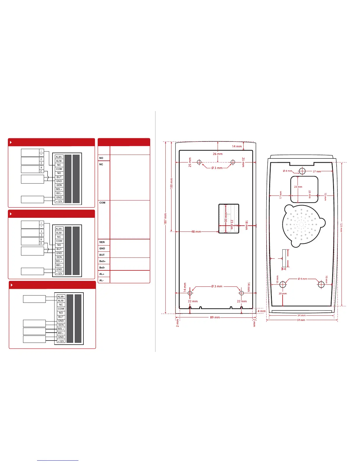
13mm
15mm
3mm
Appendix II
Terminal Dimensions and Measurements
Front View of Back Plate
Appendix I
Power Supply & Door Lock System Wiring Diagrams
Diagram 1 • Normally Close (NC)
Diagram 2 • Normally Open (NO)
Diagram 3 • Other Accessories
Door Lock Connectors
EMLock (NC)
Emergency
Break Glass (NC)
Overwrite
Keyswithch (NC)
Push Release Button
DC12V 3A
Power Supply
EMLock (NO)
Emergency
Break Glass (NO)
Overwrite
Keyswithch (NO)
Push Release Button
DC12V 3A
Power Supply
Alarm Device (NO or
NC) dry contact
Door Sensor
Doorbell
DC12V 3A
Power Supply
WIRING USAGE
PORT
Dry Contact
(independ-ent power supply for
door lock)
• NO type door lock (NO1-COM)
• NC type door lock (NC1-COM)
Power Contact
(using power from terminal to
power on door lock)
• NO type door lock (NO1-GND)
• NC type door lock (NC1-GND)
Dry Contact
(independ-ent power supply for
door lock)
• NO type door lock (NO1-COM)
• NC type door lock (NC1-COM)
Power Contact
(using power from terminal to
power on door lock)
• COM1 - +12V
Door Sensor
(SEN-GND)
Release button
(BUT-GND)
Door Bell
Alarm System
NO or NC – NO2 – Check in Advance
Options
The terminal will trigger the
alarm output (NO or NC) for the
follow-ing situations:
• Door forced open (A door
sen-sor must first be installed)
• Door open time out (A door
sen-sor must first be installed)
• Terminal has been illegally
dismantled
 Loading...