6
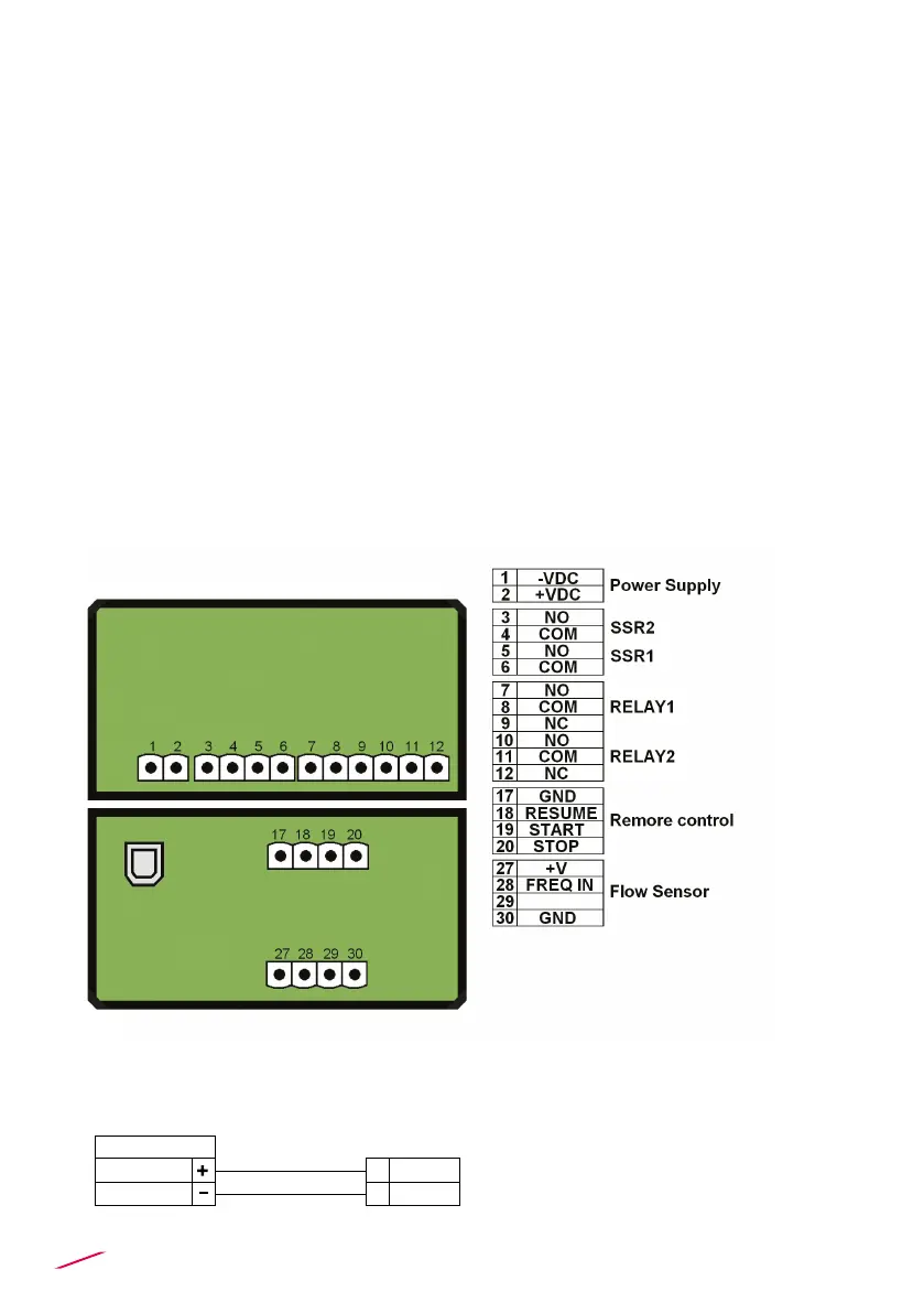
REAR TERMINAL VIEW
Wall Installation
Pull the electrical cables through liquid tight connectors.
Use electrical cables with the proper external diameter for the liquid tight
connector.
PG11/PG9: external diameter between 2-7 mm (0.079-0.276”)
Refer to dedicated sensor manual for its wiring.
• Remove the upper part of the terminals for an easy cabling.
• Insert wire tip or ferrule completely into the terminal and x with the screw
until nger tight.
• Do not route the sensor and DC power, cables in conduit containing AC
power wiring. Electrical noise may interfere with sensor signal.
• Routing the sensor cable in grounded metal conduit can help prevent
electrical noise and mechanical damage.
• Seal the cable entry points to prevent moisture damage.
• In case of malfunctioning of the instrument due to radio interferences, use
shielded cables and on the DC power cable is suggested to apply the ferrite
producing two opposite (180 °) coils on both wires (positive and negative)
POWER WIRING DIAGRAM
Power Supply
12 - 24 VDC
12 - 24 VDC
+ VDC
- VDC
2
1
 Loading...