7
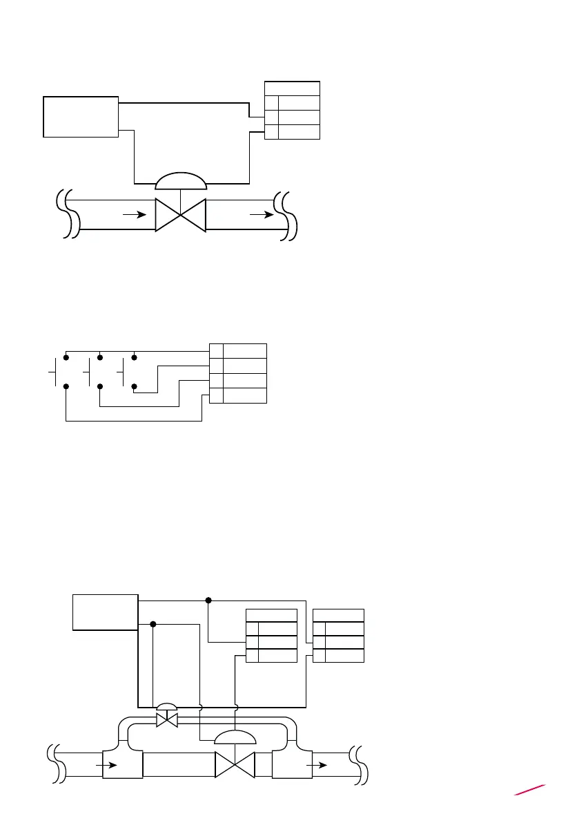
RELAY2 – BATCH RELAY WIRING DIAGRAM
REMOTE CONTROL WIRING DIAGRAM
USB PORT
Rear START, STOP and RESUME terminals are use for remote batch control
using one of next methods:
A USB port (type B) is available on the M9.50 PCB. The USB connection
allows the updating of device software. To do updating it is necessary to have:
USB cable (M9.KUSB); the interface software "FLS Calibration System” and
the new updating software for M9.50 which are both freely downloadable from
FLS website (www.snet.it) on product prole.
• Max voltage rating: 5A @ 240
VAC resistive load.
• To reduce the possibility of
noise interference, do not route
signal cables together with AC
power cable.
Mechanical switch contact
(like in the drawing)
RELAY 2
Flow Flow
AC or DC
Power
NC
COM
NO
12
11
10
STOP
START
RESUME
RESUME
GND
START
STOP
18
17
19
20
RELAY1 – OPTION RELAY WIRING DIAGRAM
A. Two Stage Shutdown Option
• Max voltage rating: 5A
@ 240 VAC resistive
load.
• To reduce the possibility
of noise interference, do
not route signal cables
together with AC power
cable.
AC or DC
Power
RELAY 1
NC
COM
NO
9
8
7
RELAY 2
NC
COM
NO
12
11
10
Bypass line
Valve
Valve
Flow
Main line
Flow
 Loading...