8
SOLID STATE RELAY 1 OR 2 –
OPTION RELAY WIRING DIAGRAM
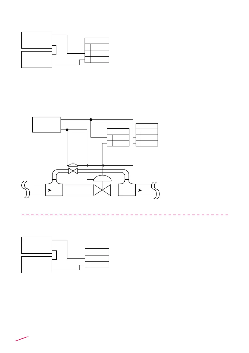
A. Two Stage Shutdown Option
B. NO Signal Alarm OR Overrun Alarm Option
B. NO Signal Alarm OR Overrun Alarm Option
• Max voltage rating: 5A @ 240 VAC
resistive load.
• To reduce the possibility of noise
interference, do not route signal cables
together with AC power cable.
• Optically isolated, 50 mA MAX sink, 24
VDC MAX pull-up voltage.
• To reduce the possibility of noise
interference, do not route signal cables
together with AC power cable.
• Same connections for SSR 2.
RELAY 1
NC
COM
NO
12
11
10
AC or DC
Power
Alarm
Device
SSR 1
COM
NO
4
3
AC or DC
Power
Alarm
Device
• Optically isolated, 50
mA MAX sink, 24 VDC
MAX pull-up voltage.
• To reduce the
possibility of noise
interference, do not
route signal cables
together with AC power
cable.
• Same connections for
SSR 2.
AC or DC
Power
SSR 1
COM
NO
4
3
RELAY 2
NC
COM
NO
12
11
10
Bypass line
Valve
Valve
Flow
Main line
Flow
 Loading...