10
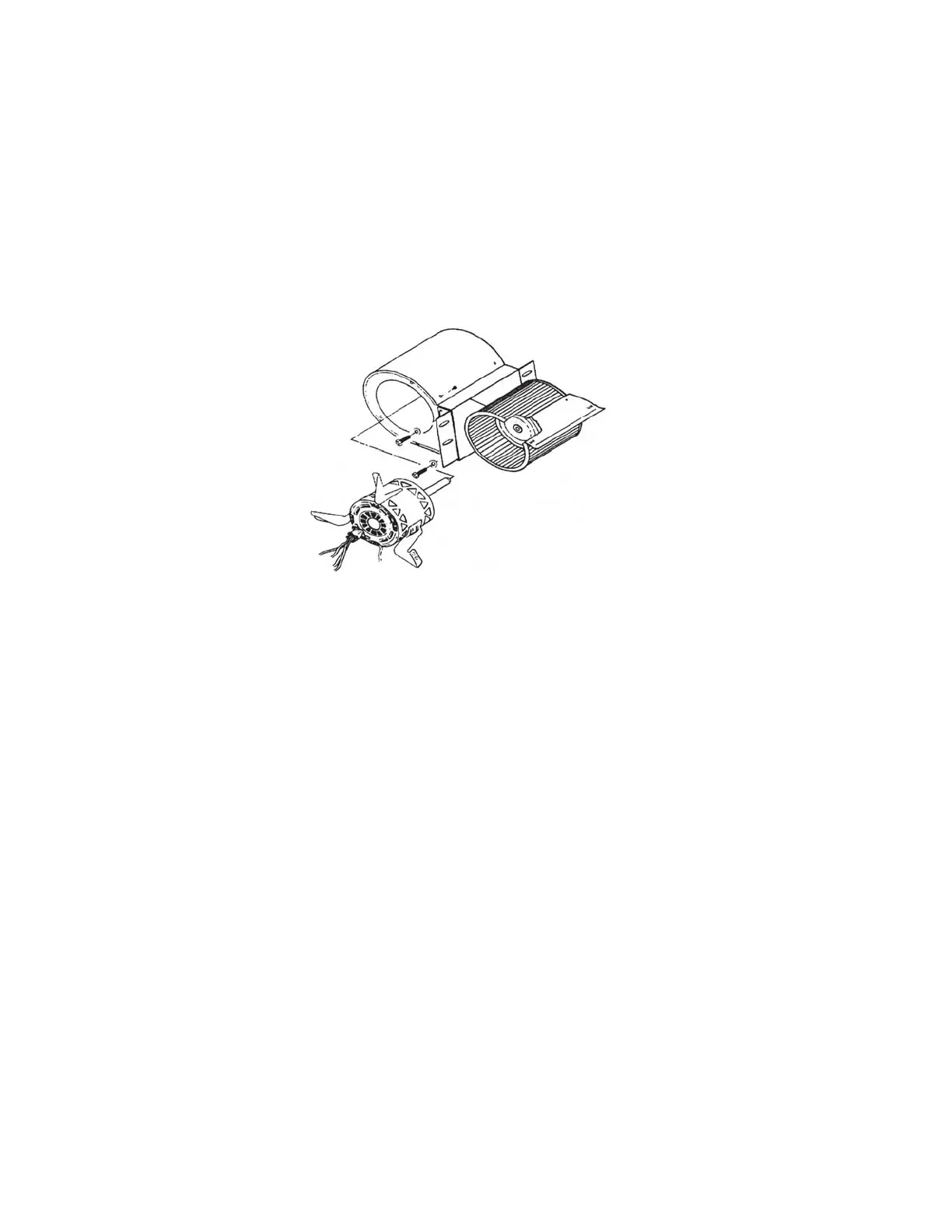
Align Blower with holes on back
side of furnace and firmly attach
with the screws provided.
Attach Blower to the left and right
mounting brackets.
ASSEMBLY INSTRUCTIONS
Please review the parts diagram and list contained on pages 14 thru 17 of this
manual to be assured that you have received all of the required components. If your
inspection reveals a discrepancy, contact your Dealer or call 800.875.4788 for help.
NOTE: for your convenience your Fire Chief has been factory assembled and the elec-
tric wiring harness is pre-wired.
BLOWER AND FILTER HOUSING
1. Fasten the right and left side angle brackets to the circulation blower using 4 each 1/4"
bolts and nuts.
2. Follow the instructions provided with the filter box for assembly. Assemble the Filter Box using the
screws provided. NOTE: The side with the electrical access hole must be mounted to the right side
of the unit.
3. Position filter box at rear of furnace. Cover rear distribution blower. Raise the filter
box approximately 4" off of the floor. Tightly press filter box to the back of the furnace
and use 8 each #10 self-tapping screws to attach it to sides of furnace.
FORCED DRAFT MOTOR
1. Mount the forced draft blower with 3 - 1/4-20 X 1/2" bolts provided.
2. Attach fan limit with 3 - #10 screws in the holes provided.
3. Mount the electrical control center with 4 #10 screws, provided.
4. Secure the flex conduit to the side of the furnace using the bracket provided.(requires 1 screw,
included).
5. Plug motor into the back of the electrical control center.
6. Connect thermostat wire (not provided #28 ga wire) to the two posts located on the side of the
control center. You may locate the wall thermostat next to you existing thermostat in the home. The
thermostat must be installed for the furnace to operate.
7. Plug the three prong grounded plug into a grounded electrical outlet.
REFER TO DIAGRAM ON PAGE 11